Chapter 3: Installation
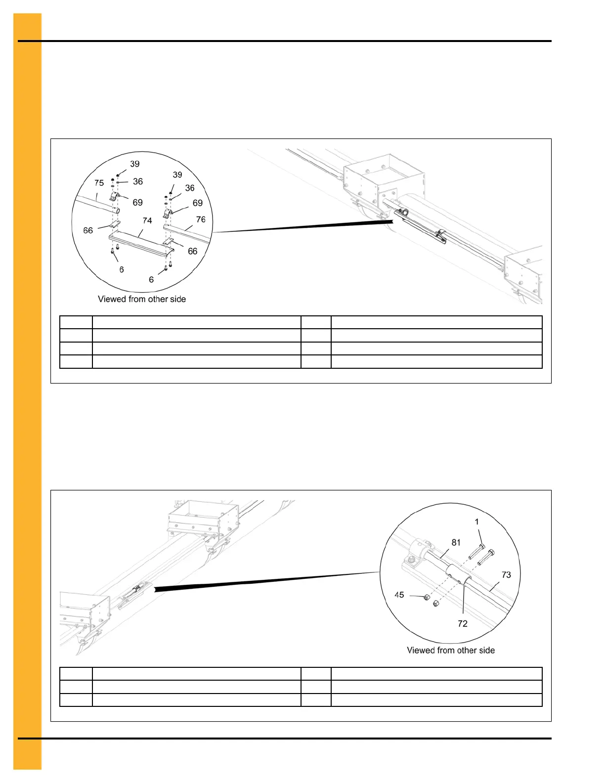
7. For 54' - 72' bins, attach the two intermediate well control rods (75 and 76) with a control rod coupler
bracket (74), control rod spacer (66) and control rod clamps (69) using two 5/16" x 1" flange bolts
(6), 5/16" flat washers (36) and 5/16" flange nuts (39).
Figure 3-13 Assembling the intermediate well control rods
6
5/16" x 1" flange bolt
69
Intermediate well control rod clamp
36 5/16" flat washer 74
Control rod coupler bracket
39
5/16" flange nut
75 Intermediate well control rod
66
Control rod spacer
76 Intermediate well control rod extension
8. Slide the two auxiliary well control rods (73 and 81) into the intermediate well control rods as shown
below and attach them with a control rod coupler (72) using two 5/16" x 1-3/4" HHTB bolts (1) and
5/16" nylock nuts (45).
NOTE: After the rods are assembled, make sure the gates operate smoothly and close completely.
Make any necessary adjustments.
Figure 3-14 Assembling the auxiliary intermediate well control rods
1 5/16" x 1-3/4" HHTB bolt 73
Auxiliary well control rod extension
45
5/16" nylock nut
81
Auxiliary well control rod
72
Control rod coupler
26
PNEG-2308 Chain Loop Power Sweep