Chapter 3: Installation
Installing the Center Well Gate
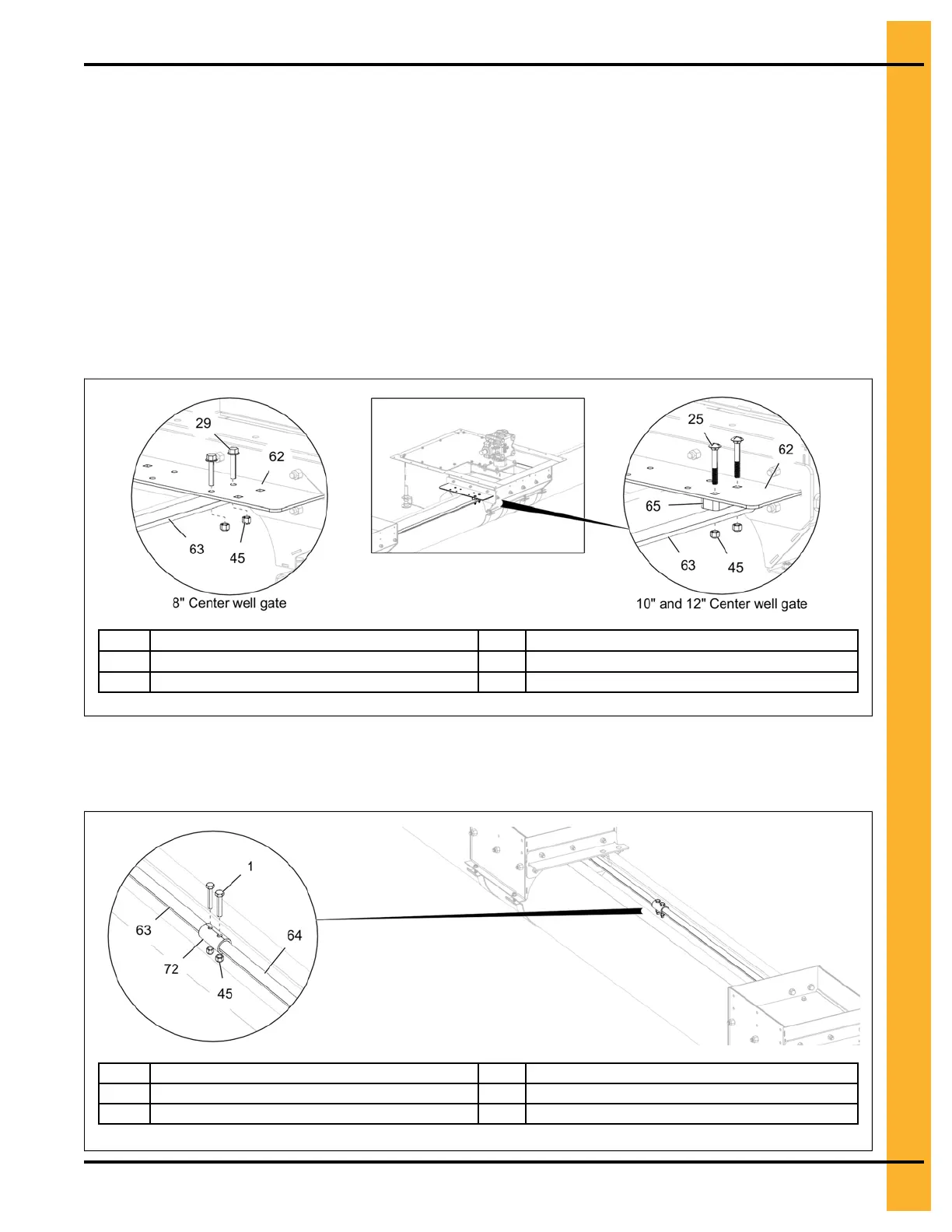
1. Slide the center well control rod (63) through the hole marked with a ‘C’ on the bin flange and
through the intermediate wells until it reaches the center well gate (62).
2. Close the center well gate (62) completely.
3. For 8" unload tube: Attach the center well control rod (63) to the bottom of the center well gate (62)
using two 5/16" x 1-1/2" flange bolts (29) and 5/16" nylock nuts (45).
For 10" and 12" unload tube: Attach the center well control rod (63) and a control rod spacer (65)
to the bottom of the center well gate (62) using two 5/16" x 2-1/4" carriage bolts (25) and 5/16"
nylock nuts (45).
Figure 3-9 Center well gate assembly
25
5/16" x 2-1/4" carriage bolt
62
Center well gate
29
5/16" x 1-1/2" flange bolt
63 Center well control rod
45
5/16" nylock nut
65
Center well control rod spacer
4. For 48'-72' bins, connect the two center well control rods (63 and 64) with a control rod coupler (72)
using two 5/16" x 1-3/4" HHTB bolts (1) and 5/16" nylock nuts (45).
Figure 3-10 Assembling the center well control rods
1 5/16" x 1-3/4" HHTB bolt 64 Center well control rod extension
45
5/16" nylock nut
72
Center well control rod coupler
63 Center well control rod
PNEG-2308 Chain Loop Power Sweep
23