Chapter 3: Installation
Installing the Rack and Pinion
Before You Begin
Before installing the rack and pinion, make sure to remove the handle (79) and lower half band (78) from
factory setting as shown in Figure 3-15, page 27 and re-install the handle (79) back as shown in
Figure 3-16, page 27. The lower half band (78) will be installed when installing the rack and pinion
assembly on the unload tube as shown in Figure 3-18, page 29.
The center well control rod only have pre-drilled holes for connecting to the center well gate. The two
holes to connect the rack and pinion assembly must be field drilled. Refer to Figure 3-17, page 28 for
center well control rod hole details.
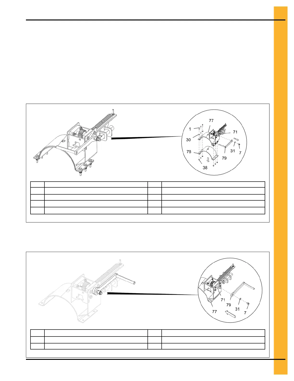
Figure 3-15 Removing the rack and pinion handle and lower half band
1
5/16" x 1-3/4" HHTB bolt
71 UHMW washer
7
3/8" x 3/4" flange bolt
77 Rack and pinion assembly
30 5/16" flat washer 78 Lower half band
31
3/8" flat washer
79 Rack and pinion handle
38 5/16" flange nut
NOTE: Use the existing 3/8" x 3/4" flange bolt (7), UHMW washer (71) and 3/8" flat washer (31) to secure
the handle (79).
Figure 3-16 Re-installing the rack and pinion handle
7
3/8" x 3/4" flange bolt
77
Rack and pinion assembly
31
3/8" flat washer
79 Rack and pinion handle
71 UHMW washer
PNEG-2308 Chain Loop Power Sweep
27