Chapter 3: Installation
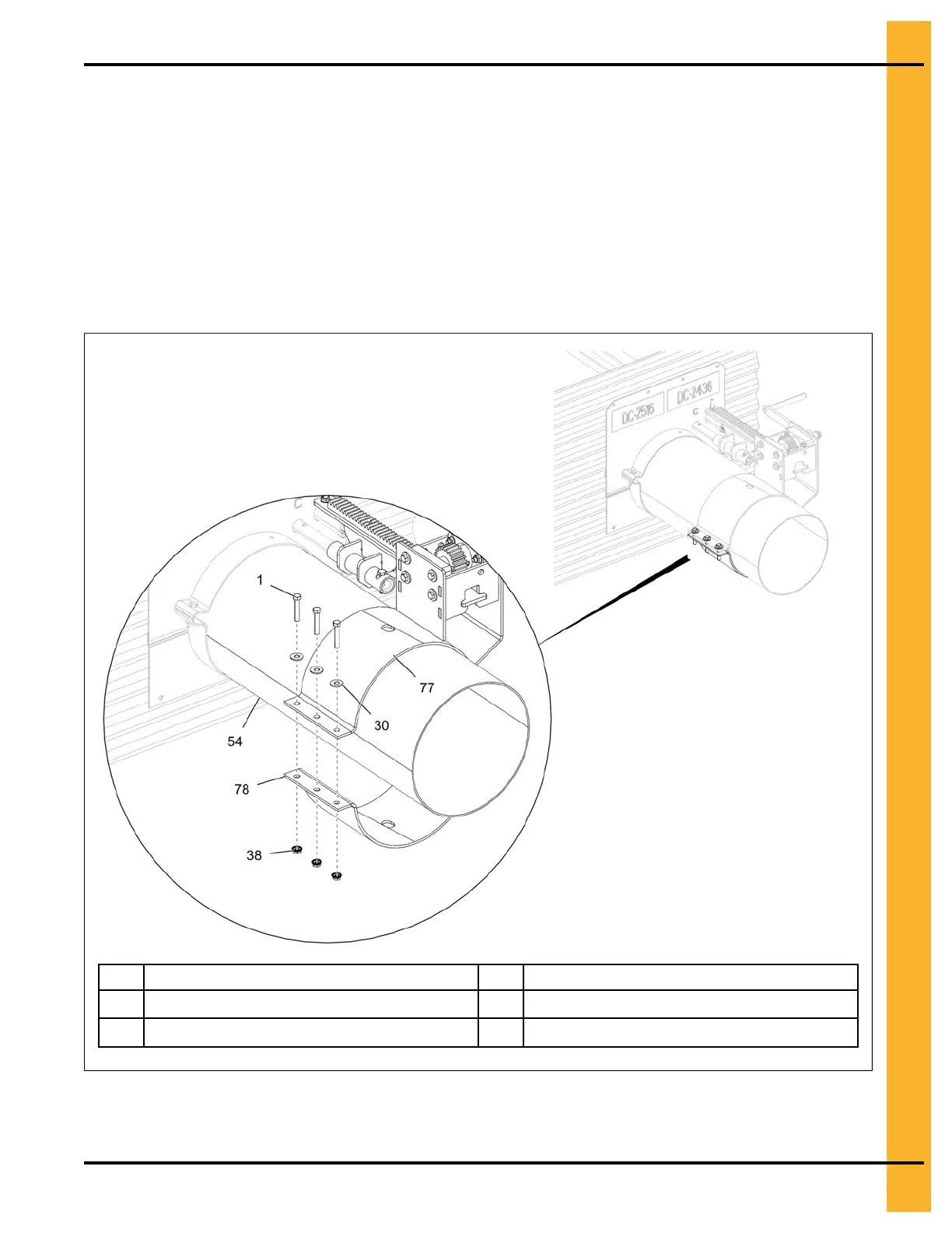
4. With the rack and pinion assembly (77) fully extended towards the bin wall, align the lower half band
(78) with the rack and pinion assembly (77) and secure it to the unload tube (54) using 5/16" x 1-3/4"
HHTB bolts (1), 5/16" flat washers (30) and 5/16" flange nuts (38).
NOTE:
a. After securing the rack and pinion assembly (77) to the unload tube (54), rotate the rack
and pinion handle to make sure all the gates open fully and smoothly. If not, make the
necessary adjustments.
b. When the gates are opened all the way, the rack bar is almost fully extended away from
the bin. The gates will bottom out on stop bolts located on the gate if installed correctly.
Figure 3-18 Installing the lower half band for rack and pinion
1
5/16" x 1-3/4" HHTB bolt
54 Unload tube
30
5/16" flat washer
77
Rack and pinion assembly
38
5/16" flange nut
78
Lower half band
After You Finish
Follow the above steps to install the rack and pinion assembly to the opposite side of the bin.
PNEG-2308 Chain Loop Power Sweep
29