Chapter 3: Installation
1. Make sure all gates are fully closed.
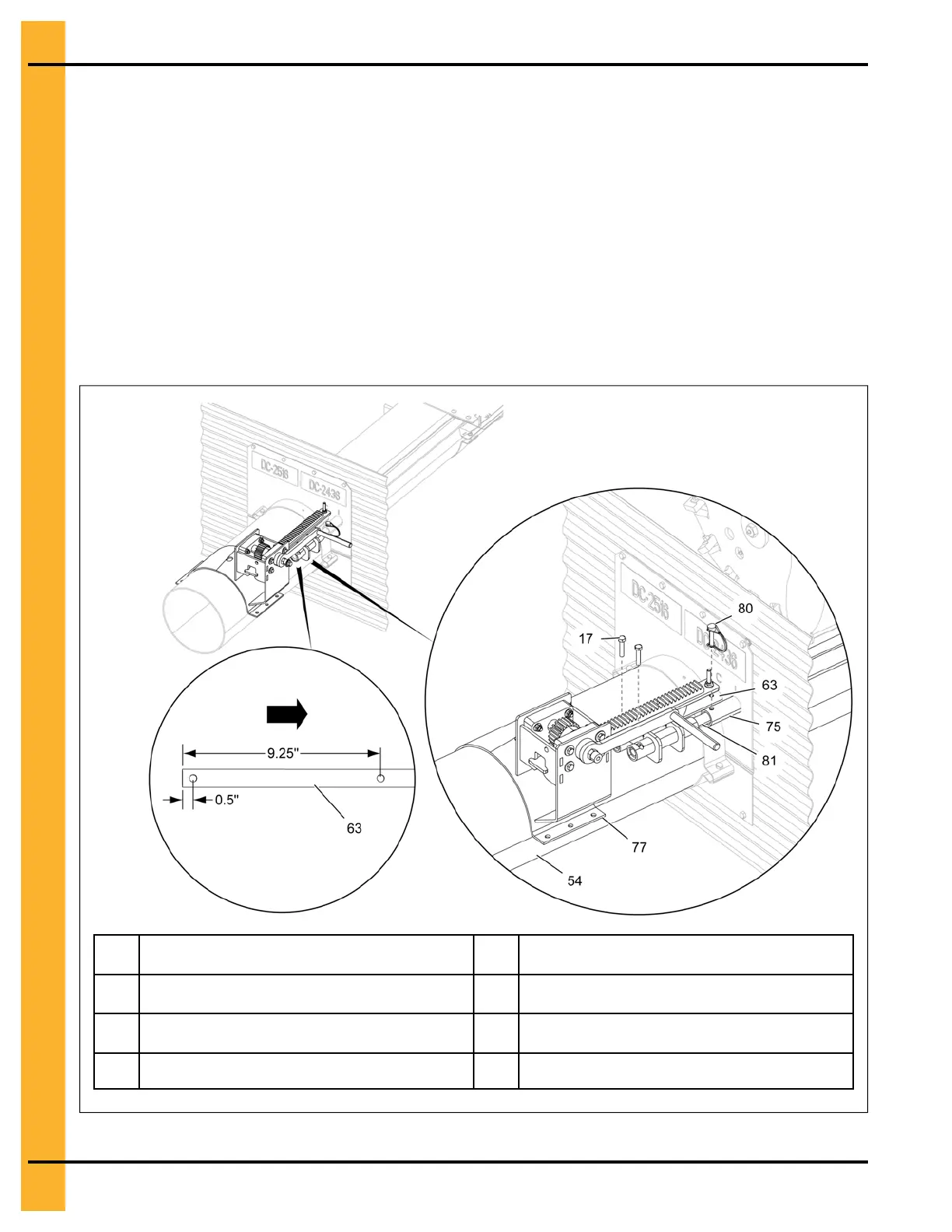
2. Slip the rack and pinion assembly (77) over the center well and intermediate well control rods (63
and 75). Align the holes, making sure the rack and pinion assembly (77) is fully extended towards
the bin wall.
NOTE: Make sure that the rack and pinion will not collide with the bin wall flange when fully
extended.
3. With rack and pinion assembly (77) resting on the unload tube (54) and tube holes aligned, place
the 5/16" x 1-1/2" HHCS bolts (17) through the center well and intermediate well control rods (63
and 75) to the rack and pinion (77) tubes.
NOTE: Place a 5/16" x 1-3/8" safety pin (80) through the intermediate well control rod (75) to the
auxiliary well control rod (81).
Figure 3-17 Installing the rack and pinion assembly
17 5/16" x 1-1/2" HHCS bolt
77
Rack and pinion assembly
54 Unload tube 80
5/16" x 1-3/8" safety pin
63 Center well control rod 81 Auxiliary well control rod
75
Intermediate well control rod
28
PNEG-2308 Chain Loop Power Sweep