Chapter 3: Installation
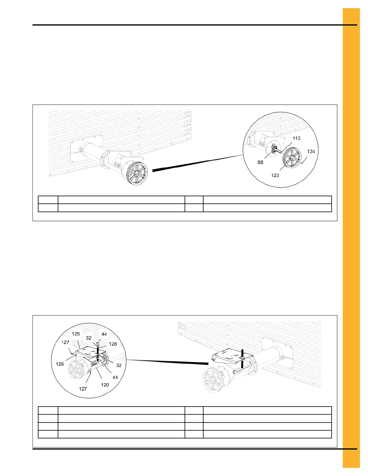
4. Install the bearing lock collar (88) over the drive shaft but DO NOT tighten the lock collar (88) at this
time.
5. Slide the sheave (123) over the drive shaft (113) close to the bearing assembly. Once the sheave
(123) is set at the correct position, secure the sheave (123) using the square key (124). Tighten the
lock collar (88) on the bearing and then the set screws in the sheave (123).
Figure 3-50 Installing the sheave to the drive shaft
88
Bearing lock collar
123 Sheave
113 Drive shaft 124
Square key
6. Install the adjustment weld rod (128) to the tube assembly (120) using cotter pins (127).
7. Install one end of motor mount plate (125) to the support plate of the tube assembly (120) using
motor mount pivot rod (126) and cotter pins (127).
8. Install the other end of the motor mount plate (125) to the adjustment weld rod (128) with 3/4" flat
washers (32) and 3/4" hex nuts (44). This rod allows for the adjustment of the motor mount plate
(125).
Figure 3-51 Installing the motor mount plate
32 3/4" flat washer 126
Motor mount pivot rod
44 3/4" hex nut 127
Cotter pin
120
Discharge tube assembly
128
Adjustment weld rod
125
Motor mount plate
PNEG-2308 Chain Loop Power Sweep
51