Chapter 3: Installation
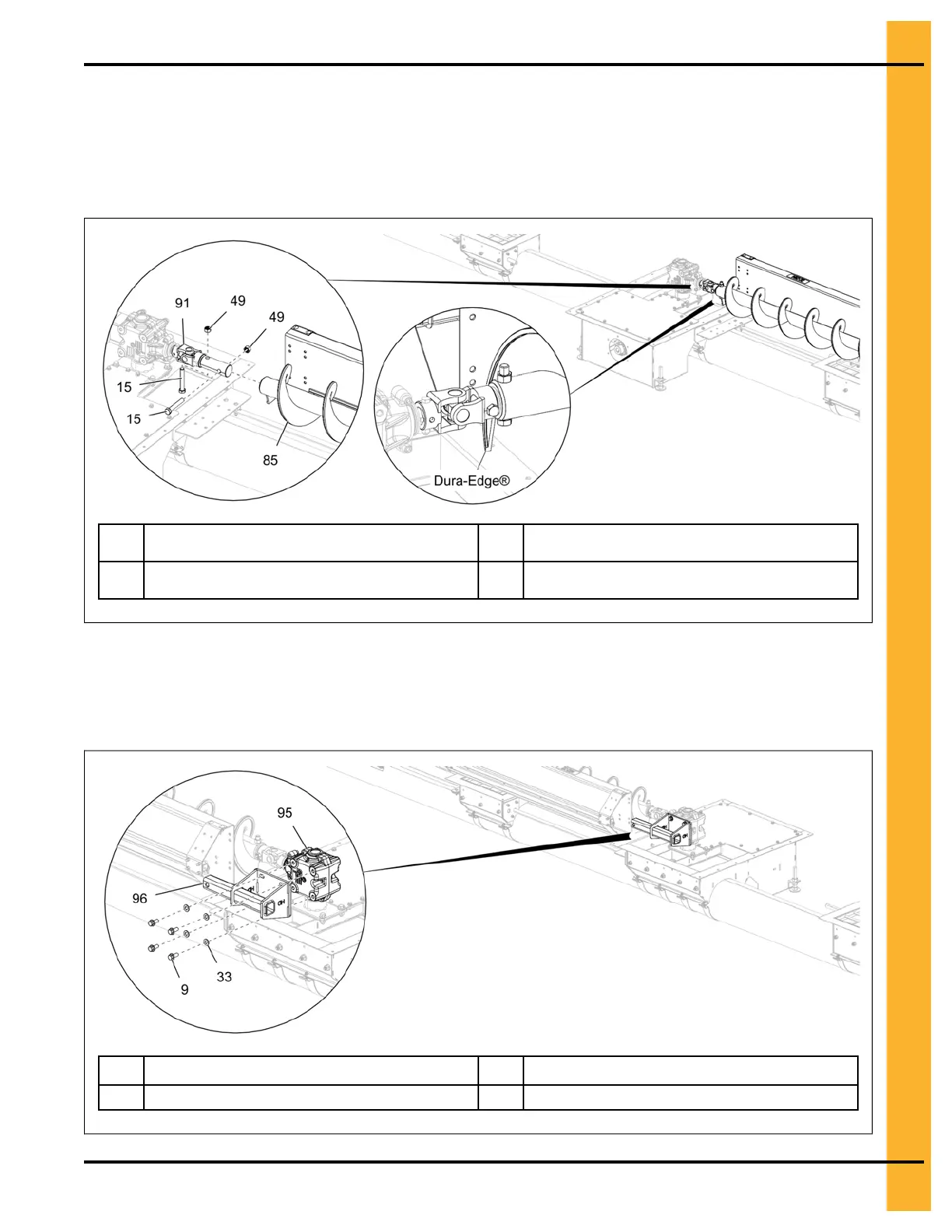
3. Attach the first flight section (85) to the U-joint (91) shaft. Make sure that the Dura-Edge® side of the
flight (85) faces the center of the bin. Secure it with two 5/8" x 4" HHCS bolts (15) and 5/8" stover
nuts (49).
Figure 3-25 Attaching the auger to the U-joint
15
5/8" x 4" HHCS bolt
85 Flight section
49 5/8" stover nut 91 U-joint
4. Attach the pivot bracket (96) to the side of the top gearbox (95) using four 1/2" x 1-1/4" flange bolts
(9) and 1/2" flat washers (33).
NOTE: Do not tighten the flange bolts (9).
Figure 3-26 Attaching the pivot bracket to the gearbox
9
1/2" x 1-1/4" flange bolt
95 Top gearbox
33
1/2" flat washer
96 Pivot bracket
PNEG-2308 Chain Loop Power Sweep
35