Chapter 3: Installation
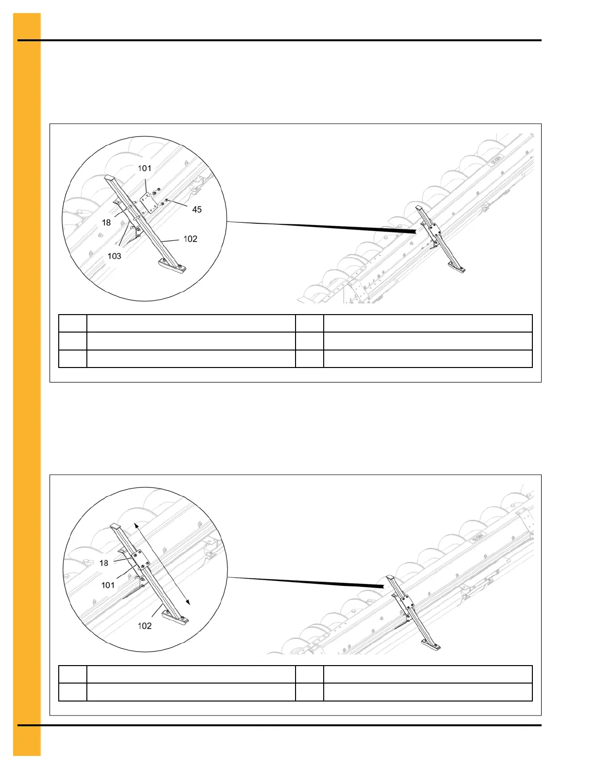
1. Install the backshield support assembly (102) to the torque tube bracket (103) using mounting plate
(101), four 5/16" x 2" HHCS bolts (18) and 5/16" nylock nuts (45).
Figure 3-33 Installing the backshield support assembly
18
5/16" x 2" HHCS bolt
102 Backshield support assembly
45
5/16" nylock nut
103 Torque tube bracket
101 Mounting plate
2. The backshield support assembly (102) can be adjusted in the direction (as shown) for proper
sweep clearance.
NOTE: When sliding the support down closer to the floor, it will raise the sweep off the floor and put
down pressure onto the reduction wheel. Adjust until the backshield is level front to back.
Figure 3-34 Adjusting the backshield support assembly
18
5/16" x 2" HHCS bolt
102 Backshield support assembly
101 Mounting plate
40
PNEG-2308 Chain Loop Power Sweep