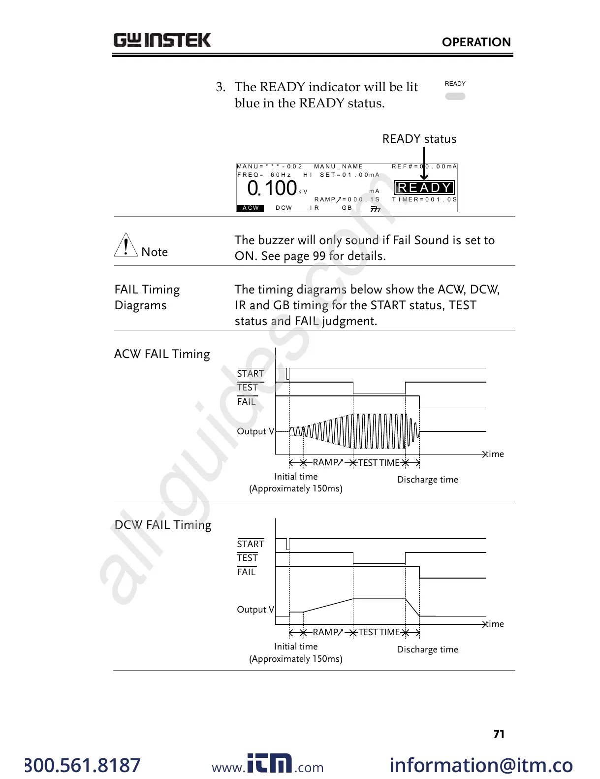
3. The READY indicator will be lit
blue in the READY status.
I R G B
m A
A CW D CW
E
F R E Q = 0 H z 6
0
100
k V
AER
MT I E = 0 0 1 . 0 SR
0 0 m AER F =# 0 .0
1 . 0 0 m AIH ES = 0T
0 0 . 1 S0A M P =R
D
MM A UN N A_2M A N U = * * * - 0 0
READY status
Y
The buzzer will only sound if Fail Sound is set to
ON. See page 99 for details.
The timing diagrams below show the ACW, DCW,
IR and GB timing for the START status, TEST
status and FAIL judgment.
START
TEST
FAIL
Discharge time
Output V
time
Initial time
RAMP
TEST TIME
(Approximately 150ms)
FAIL
Discharge time
Output V
time
Initial time
RAMP
START
TEST
TEST TIME
(Approximately 150ms)
w ww . . co m
information@itm.com1.800.561.8187
All manuals and user guides at all-guides.com
all-guides.com
 Loading...