1-7
2) Rear view
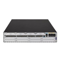
Figure 1-6 Rear view of MSR 30-20
(1)
(2) (6)
(4) (3)
(5)
(7)
(8)
(12)(11)(10)
(13)(14)(9)
(1) GE interface 0 (2) GE interface 1
(3) SIC slot 1 (4) SIC slot 2
(5) SIC slot 3 (6) SIC slot 4
(7) MIM slot 5 (8) MIM slot 6
(9) Grounding terminal (10) VCPM LED
(11) VPM1 LED (12) VPM0 LED
(13) ESM0 LED (14) ESM1 LED
Panel LEDs
Table 1-9 Front panel LEDs description of MSR 30-20 router
LED Description
PWR
Power LED:
ON means the system provides power for cards normally.
OFF means the system does not supply power for cards.
SYS
Hardware system operation LED:
Blinking means the system is operating normally.
Steady ON or steady OFF means the system does not operate normally.
USB0
OFF means the USB interface has not been connected to a host.
Steady green means the USB interface is connected to a host and the host can be
removed.
Blinking green means data is being transferred to/from the host and the host cannot
be removed now.
CF
CF card LED:
Steady green means the CF card is in the slot and can be identified by the router.
Blinking green means the CF card is being accessed and cannot be removed.
Steady yellow means the CF card is in the slot but cannot be identified by the router.
OFF means no CF card is inserted or the CF card cannot be identified.
Table 1-10 Rear panel LEDs of MSR 30-20 Router
LED Description
GE LED
OFF means no link is present.
Steady green means a 1000 Mbps connection has been established.
Blinking green means data is being received or transmitted at a speed of 1000 Mbps.
Steady yellow means a 10/100 Mbps connection has been established.
Blinking yellow means data is being received and transmitted at a speed of 10/100
Mbps.
 Loading...