6-6
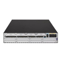
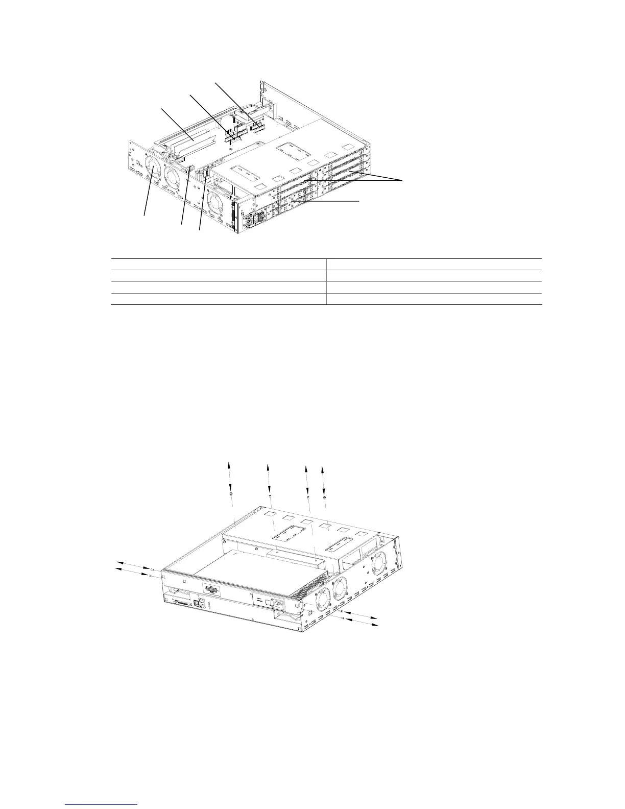
Figure 6-10 Internal structure of the MSR 30-40/30-60 (After the power module is removed)
(1)
(2)
(3)
(4)
(5)
(6)
(7)
(8)
(1) VPM (2) ESM slot 0
(3) ESM slot 1 (4) MIM card slot
(5) SIC card slot (6) Memory module slot
(7) VCPM slot (8) Fan module
Removing/Installing a Power Module
This section illustrates how to remove the power module from the MSR 30-40/30-60. For the other
modules, only step 1 applies.
1) Remove the power bracket from the router.
z Remove the screws from the power bracket.
Figure 6-11 Remove the screws from the bracket
z Draw out the power bracket and remove the power cord from the main board.
 Loading...