3-6
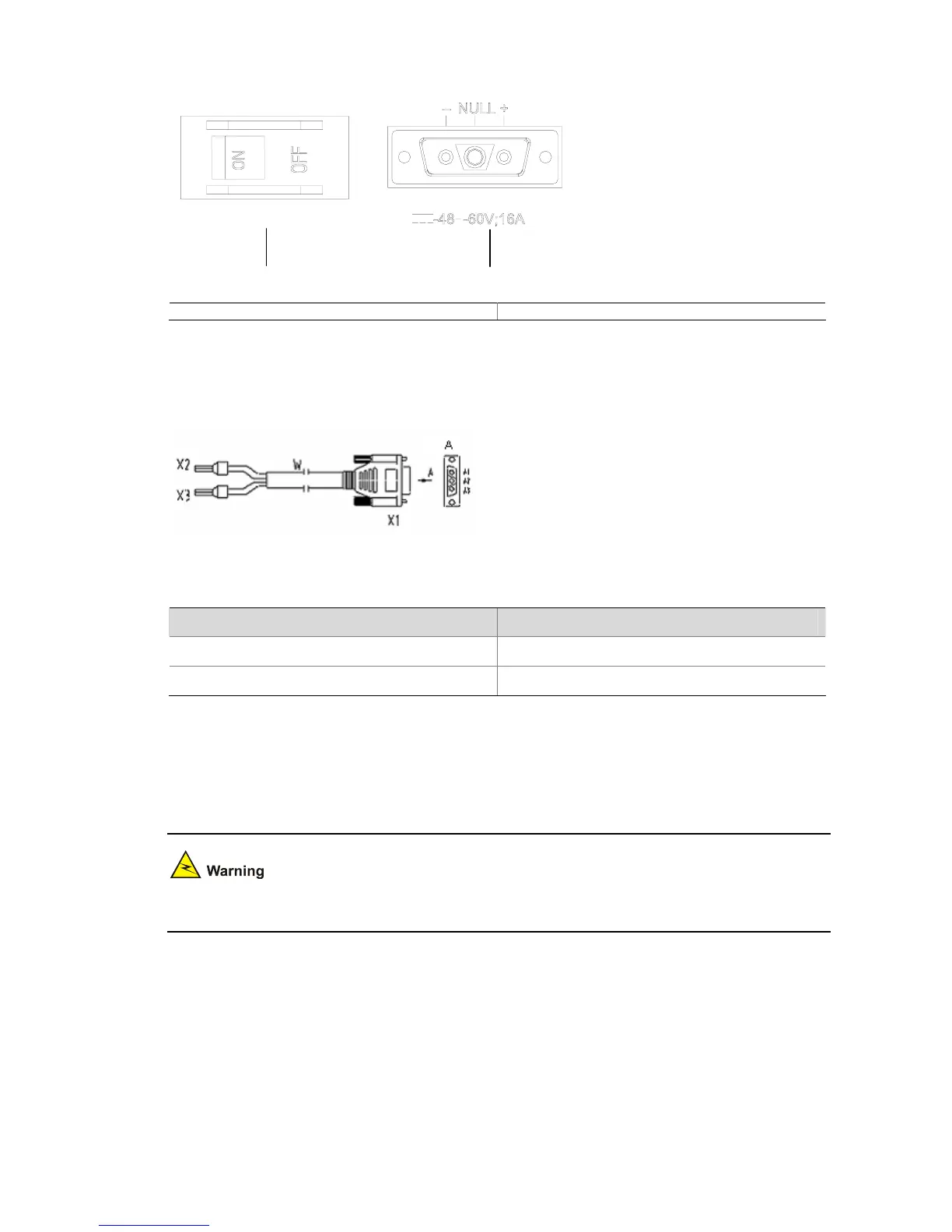
Figure 3-6 Power socket on DC-powered routers
(1)
(2)
(1) Power switch (2) DC input
Connecting the DC power cord
Figure 3-7 Sketch map of DC power cord
Table 3-3 Connection of the DC power cord between the DC power supply and the router
–48 VDC power supply Router
X2 (–48 VDC connector, blue) X1.A1
X3 (BGND connector, black) X1.A3
Step 1: Make sure that the PGND is properly grounded to the earth.
Step 2: Insert one end of the DC power cord accompanying the router into the power socket on the
chassis rear panel. Then connect the other end of the power cord (with a BGND connector and a –48
VDC connector) to a –48 VDC power supply.
When connecting the DC power cord, notice the labels on the power cord to avoid wrong connection.
Step 3: Check the POWER LED on the front panel of the router. ON indicates correct connection.
 Loading...