4-8
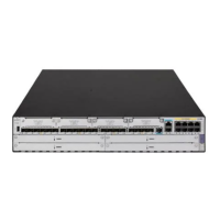
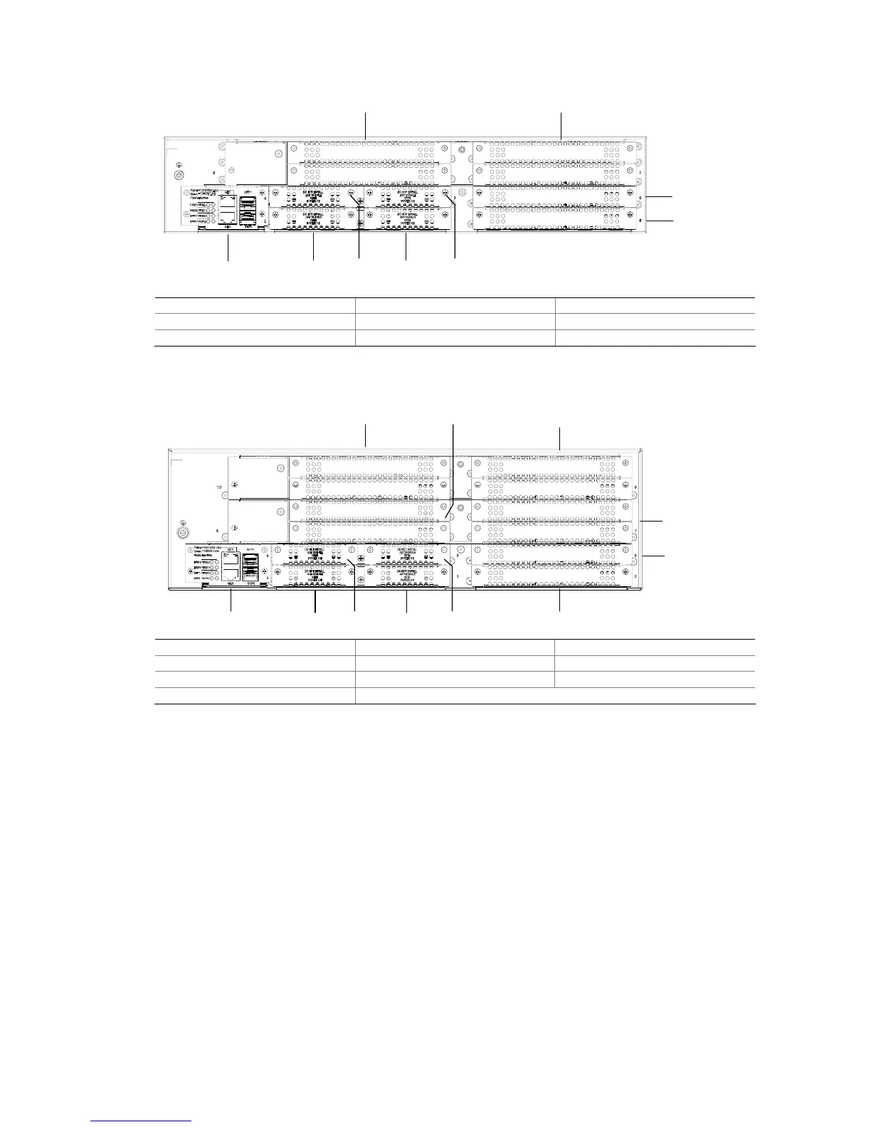
Figure 4-8 Slot arrangement on the MSR 30-40
(1)
(2)(3)
(7)
(6)
(8)(9)
(4)(5)
(1) Slot 0 (2) Slot 1 (3) Slot 2
(4) Slot 3 (5) Slot 4 (6) Slot 5
(7) Slot 6 (8) Slot 7 (9) Slot 8
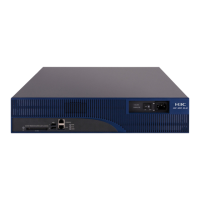
Figure 4-9 Slot arrangement on the MSR 30-60
(1)
(2)(3)
(7)
(6)
(8)
(10)
(11) (9)
(5) (4)
(1) Slot 0 (2) Slot 1 (3) Slot 2
(4) Slot 3 (5) Slot 4 (6) Slot 5
(7) Slot 6 (8) Slot 7 (9) Slot 8
(10) Slot 9 (11) Slot 10
Interface numbering
The MSR 30 Series Router interface adopts “two dimension” numbering rules, shown in the following:
z The interfaces are represented by interface-type X/Y, where interface-type can be serial,
asynchronous, ethernet or ATM, and so on; X specifies the slot number; Y specifies the interface
number.
z Different interfaces on an interface module share the same slot number X.
z For every interface, Y starts from 0 and indicates the interface sequence on the interface module,
from left to right.
If you install a MIM-1FE and an MIM-2FE respectively in slot 5 and slot 6 on the MSR 30-20, the
Ethernet interfaces are numbered as follows:
z Fixed Gigabit Ethernet interfaces are Gigabit Ethernet 0/0 and Gigabit Ethernet 0/1;
z The Ethernet interface on the FIC-1FE is Ethernet 5/0;
z The Ethernet interfaces on FIC-2FE are Ethernet 6/0 and Ethernet 6/1.
 Loading...