Installation Manual
H3C S3600 Series Ethernet Switches Chapter 3 Installation
3-2
Note:
z When the depth of a switch is greater than 300 mm (11.8 in), the front mounting ears
only secure the switch rather than bear its weight.
z Guide rails purchased from H3C apply only to standard cabinets 1,000 mm (39.4 in)
deep. Use other supports to substitute for guide rails in the case of other cabinet
depths.
I. Introduction to mounting ear
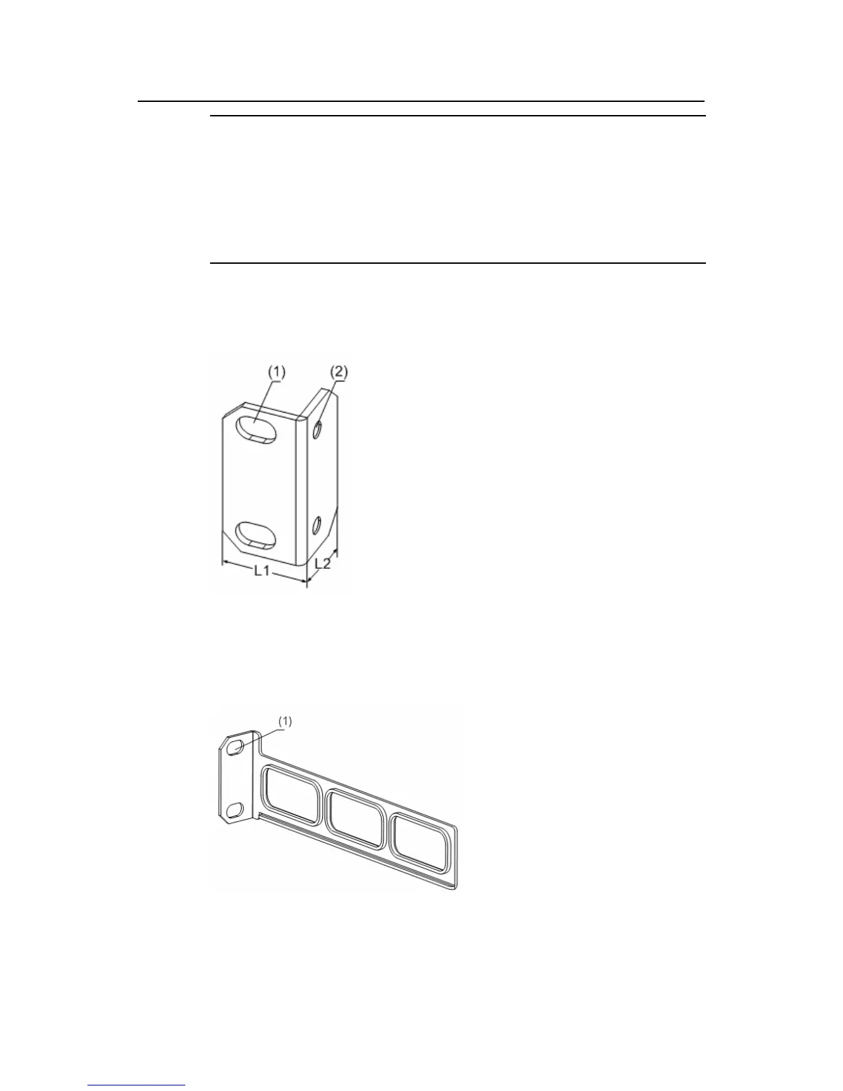
Figure 3-1 shows the appearance of a front mounting ear.
(1): Screw hole used to fix the mounting ear to the cabinet (Use one M6 screw)
(2): Screw hole used to fix the switch to the mounting ear
Figure 3-1 Appearance of a front mounting ear
Figure 3-2 shows the appearance of a rear mounting ear.
(1): Screw hole used to fix the mounting ear to the cabinet (Use one M6 screw)
Figure 3-2 Appearance of a rear mounting ear

 Loading...


