Installation Manual
H3C S3600 Series Ethernet Switches Chapter 3 Installation
3-7
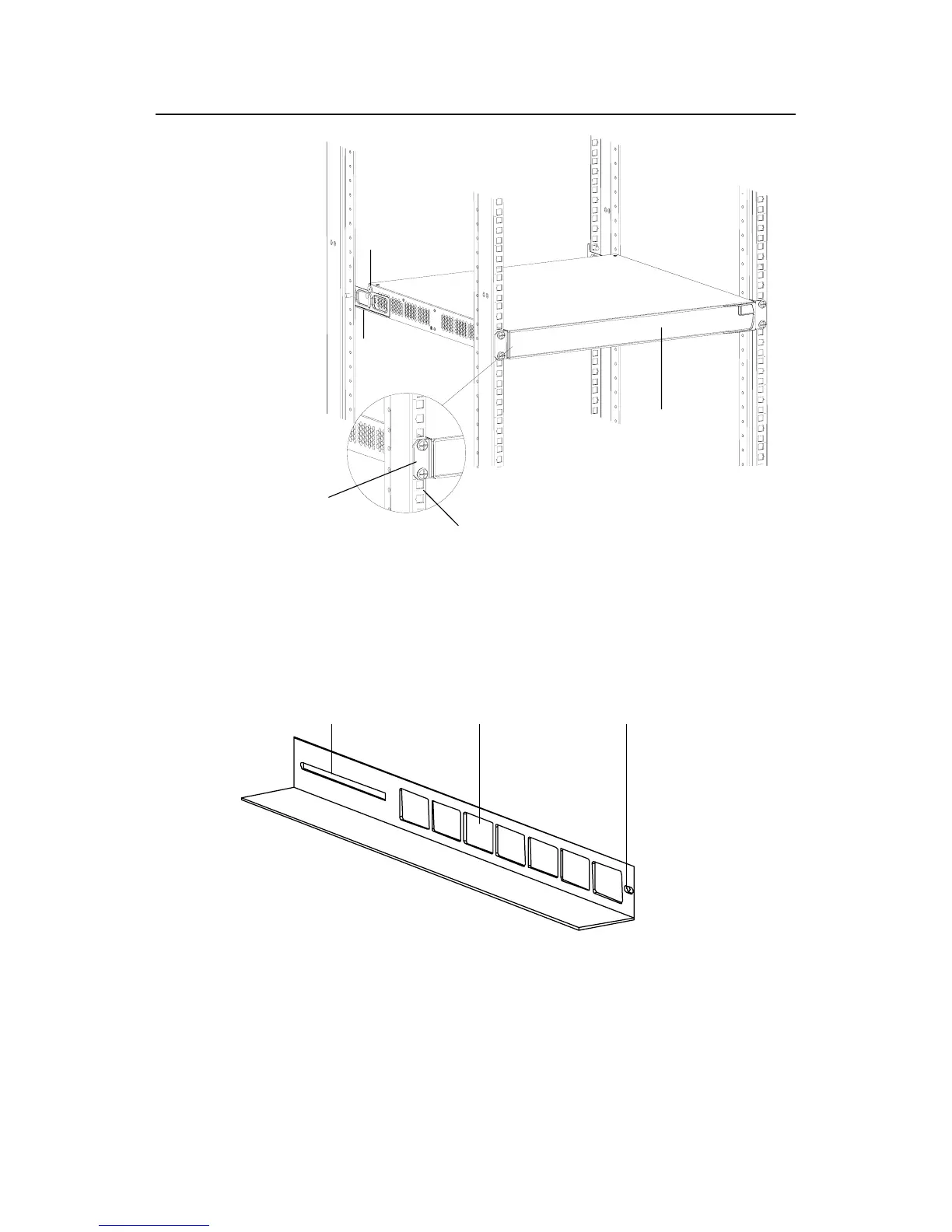
Front panel
Screw 1
Rear
mounting ear
Front square-holed bracket
Front mounting ear
Screw 1: Load-bearing screw
Figure 3-9 Effect diagram of front and rear mounting ear installation (2)
V. Use front mounting ears and guide rails
z Introduction to guide rail
Figure 3-10 shows the appearance of a guide rail.
Slotted hole 1 Cooling hole Slotted hole
Slotted hole 1: Used to fix the guide rail to the rear bracket. You can adjust the screw hole
position according to the position of the switch.
Cooling hole: Used for heat dissipation between switch and cabinet
Slotted hole 2: Used to fix the guide rail to the front bracket
Figure 3-10 Appearance of a guide rail

 Loading...


