Do you have a question about the Hach Ultra Low Range CL17sc and is the answer not in the manual?
Details on physical dimensions, enclosure, weight, mounting, and protection for the analyzer.
Specifications for sample water pressure, flow rate, temperature, and filtration.
General safety warnings, precautions, and hazard symbol explanations.
Instructions to read and observe all instrument labels and tags for personal safety.
Details on FCC and Canadian ICES regulatory compliance for the analyzer.
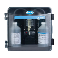
Overview of the analyzer and its main components, including measurement cycle lights.
Explanation of the status light colors (Green, Yellow, Red) and their meanings.
Identification of the analyzer and included installation/tubing kits.
Defines the intended application and target users for the analyzer.
General guidelines for installing the analyzer, covering location and environment.
Explanation of icons used in installation diagrams.
Instructions for performing an optional air purge for the analyzer.
Detailed steps for mounting the analyzer and connecting plumbing.
Guidelines for selecting an optimal sampling point for accurate readings.
Specifications for sample water to ensure proper instrument performance.
Proper installation guidelines for drain lines to prevent damage.
Instructions for installing the stir bar and the analyzer's tubing harness.
Step-by-step guide for safely installing reagent bottles.
Procedure for opening shut-off valves and starting sample flow.
Instructions for connecting the analyzer to the controller.
Guidance on connecting the SC controller to a power source.
Instructions for connecting external devices to the SC controller.
Steps for setting up and priming the analyzer, including sensor scanning.
Instructions on how to set the correct sample flow rate.
Steps to ensure the SC Controller has the most current software.
Guide to configuring analyzer settings like name, units, averaging, and alarms.
Refer to controller documentation for system configuration.
Refer to controller documentation for keypad and navigation details.
How to view CL2 exposure data and trend charts on the controller.
Information on accessing and understanding data, event, and service logs.
Information source for Modbus registers for network communication.
Procedure for measuring a grab sample for verification or analysis.
Recommended schedule for routine maintenance tasks for the analyzer.
Detailed instructions for cleaning the analyzer's cell.
Step-by-step guide for safely replacing reagent bottles.
Instructions for cleaning the Y-strainer screen to resolve flow issues.
Procedure for preparing the analyzer for extended periods of non-use.
Steps for properly preparing the analyzer for shipping.
Instructions for cleaning the exterior of the analyzer.
Procedure for safely cleaning up chemical spills.
Troubleshooting guide for errors indicated by a red status light.
Troubleshooting guide for warnings indicated by a yellow status light.
List of consumable items for the analyzer, including item numbers.
List of approved replacement parts for the analyzer, including item numbers.
List of available accessories for the analyzer, including item numbers.
| Measurement Method | Colorimetric DPD method |
|---|---|
| Power Requirements | 100-240 VAC, 50/60 Hz |
| Resolution | 0.01 mg/L |
| Accuracy | ±0.03 mg/L or ±5% of reading, whichever is greater |
| Sample Temperature | 5 to 50 °C |
| Cycle Time | 5 minutes |
| Sample Flow Rate | 200 mL/min |
| Outputs | 4-20 mA |
| Operating Temperature | 5 to 40 °C |
| Response Time | 5 minutes |