14 6LE005550A
Description of the h3+ communication system
2.1 h3+ electronic trip units
2.1.2
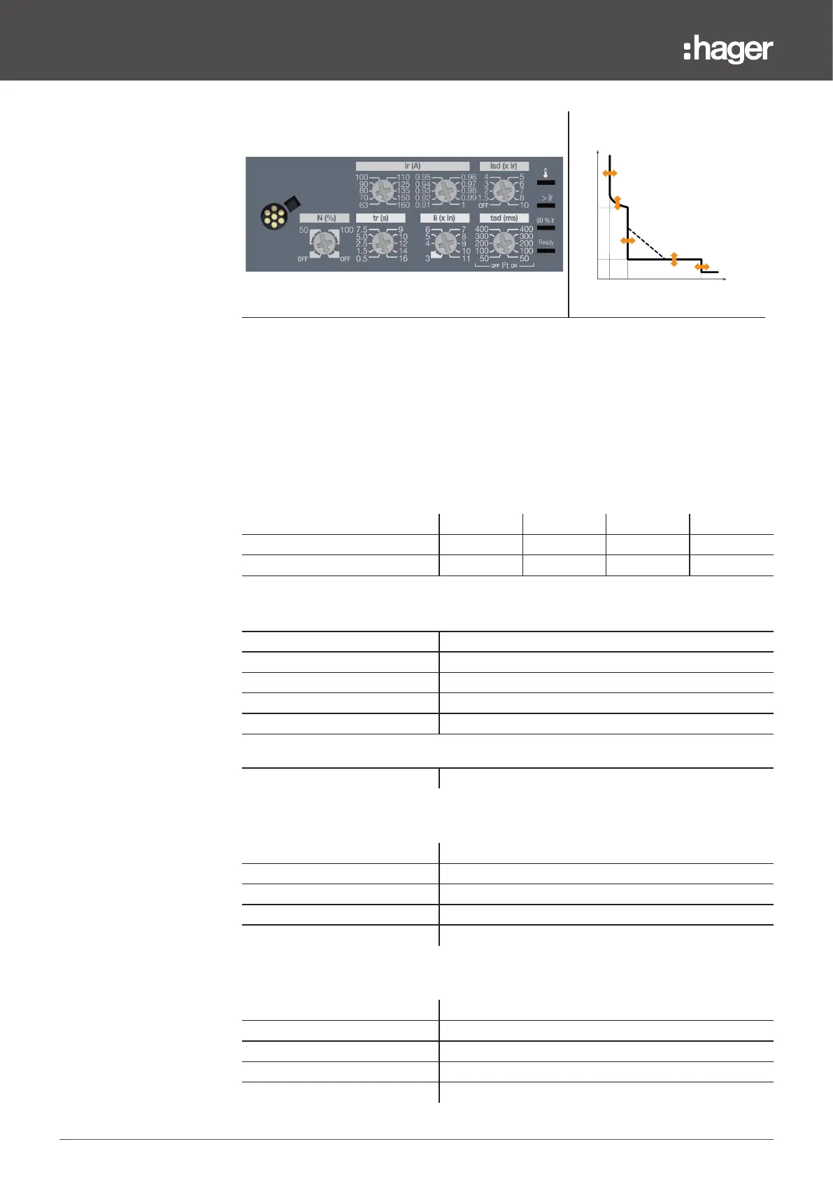
LSI trip units
tr
lr lilsd
tsd
l²t
In (A)
t (s)
- Configuration using adjustment dials.
- Signalling the status of the trip unit via LED (Ready).
- Signalling the PTA overload pre-alarm via LED (threshold 90% Ir).
- Signalling the overload alarm via LED (>Ir).
- Signalling the trip unit temperature alarm via LED.
- Possible adjustment of time delays and thresholds. The instantaneous
trip time is fixed.
- Possible adjustment of the neutral pole protection on 4-pole versions
(neutral positioned on the left).
40 A 100 A 160 A 250 A
P160 X X X -
P250 X X X X
L - Long time delay protection
Ir (tripping between 1.05 and 1.20 x Ir)
Ir1 (A) In = 40 A 16 - 18 - 20 - 22 - 25 - 28 - 32 - 34 - 37 - 40
Ir1 (A) In = 100 A 40 - 45 - 50 - 57 - 63 - 72 - 80 - 87 - 93 - 100
Ir1 (A) In = 160 A 63 - 70 - 80 - 90 - 100 - 110 - 125 - 135 - 150 - 160
Ir1 (A) In = 250 A 90 - 100 - 110 - 125 - 140 - 160 - 180 - 200 - 225 - 250
fine adjustment Ir2 0.91 - 0.92 - 0.93 - 0.94 - 0.95 - 0.96 - 0.97 - 0.98 - 0.99 - 1
tr (accuracy -21%/+1%)
tr (s) at 6 x Ir 0.5 - 1.5 - 2.5 - 5 - 7.5 - 9 - 10 - 12 - 14 - 16
S - Short time delay protection
Isd (accuracy -10/+10%)
Isd adjustment = Ir x … OFF - 1.5 - 2 - 3 - 4 - 5 - 6 - 7 - 8 - 10
tsd (ms) at 10 x Ir and I²t OFF 50 100 200 300 400
tsd (ms) at 10 x Ir and I²t ON 50 100 200 300 400
non-tripping time (ms) 20 80 180 280 380
maximum cut-o time (ms) 80 150 250 350 450
I - Instantaneous protection
Ii (accuracy +15/-15%)
In = 40 A; 100 A: Ii (x In) 3 - 4 - 5 - 6 - 7 - 8 - 10 - 12 - 15
In = 160 A; 250 A: Ii (x In) 3 - 4 - 5 - 6 - 7 - 8 - 9 - 10 - 11
time delay (ms) fixed
non-tripping time (ms) 10
maximum cut-o time (ms) 50