26 6LE005550A
Function of the Energy trip unit
3.1 Energy trip unit navigation and settings
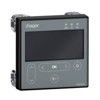
The front face of the Energy electronic trip unit groups together the following elements:
1 2 3 4 5 6
Key
1
MIP connector
2
h3+ joystick
3
Embedded display
4
Unlock button
5
Ir max ajustment dial
6
Indicator LEDs
The embedded display enables the settings of the Energy trip unit to be accessed and
the measurements and statuses to be viewed by means of the following 4 main menus:
Protection Measurements Configuration Information
3.1.1
Protection menu
The Protection menu is composed of sub-menus in order to display and modify
each protection setting for the trip unit:
Threshold setting Time setting Other setting
Long time delay
protection
Short time delay
protection
Instantaneous protection
Ground fault protection
Neutral protection