96 6LE005550A
Starting, commissioning, operation
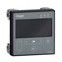
4.6 Start-up and configuration via the HTD210H display
4.6.3
HTD210H display supply
The 24 VDC supply to the HTD210H display must come from an external supply.
The external 24 VDC supply is connected in two ways:
- From the communication module connection if installed.
- From the HTC140H 24 V CIP adapter connection.
To connect the communication module, see § 4.3.
To connect the CIP-24 V adapter, perform the following procedure.
Action Note/Illustration
1 Switch the Energy circuit
breaker to the OFF or
tripped position.
-
2
Open the front cover of the
circuit breaker
The front cover of the circuit breaker can only be opened in the
OFF or tripped position.
3 Insert the CIP marked
section of the HTC140H
adapter in the free CIP
connector inside the circuit
breaker on the left-hand
side
Risk of damaging the CIP connector. Respect the direction of
insertion for the connector: The adapter part marked CIP must
be visible from the front. Avoid forcing the connector when
inserting
4 Route the cable for the
HTC140H adapter with
the CIP adapter cable
along the left-hand side
cable channel of the circuit
breaker provided for this
purpose.
If necessary, use the side
support supplied with the
circuit breaker to connect
the cable to the side wall.
It is advisable to provide a 24 V connection terminal near the
circuit breaker to connect the + and – wires of the HTC140H
adapter.
The wiring of the 24 VDC circuit may be extended from this
terminal up to the 24 VDC supply terminals.
+ wire: Brown colour
- wire: White colour
Please respect the wiring rules in force in switchboards:
- Separate the routing of the power cables and the circulation
of low-level signal cables
- Secure the cable along the routing.
5 Close the front cover
of the circuit breaker to
immobilise the side support
as well as the side cable
routing.
-