89
b) Place 1/2-in (M12) flanged nut (flange toward pump shaft) between pump shaft
and puller drive screw (protects shaft threads).
c) Using a wrench (or socket and ratchet), tighten puller drive screw until impeller
comes loose.
d) Remove 1/2-in (M12) flanged nut and puller.
Then pull impeller off pump shaft by hand. 3.
Remove impeller/pump shaft key. 4.
D. Inspect and clean all components. See paragraph 5.7.7, Cleaning And In-
spection Guidelines on page 51.
If inspection indicates the clearance rings require replacement see para-1.
graph 5.8.7.2, Pump Clearance Ring R&R on page 110.
If inspection indicates the mechanical seal requires replacement see 2.
paragraph 5.8.4.9, Mechanical Seal R&R on page 90.
If inspection indicates the pump shaft oil seal requires replacement see 3.
paragraph 5.8.4.13.1, Pump Shaft Oil Seal And O-ring on page 102.
Impeller Installation
A. Remove mechanical seal spring.
B. Install impeller key in pump shaft keyway. (Use small amount of grease to
hold key in place.)
C. Install mechanical seal spring.
D. Apply a heavy coating of grease to impeller ends.
NOTE
The grease protects the clearance ring during the initial pump priming to prevent the
ring from contacting the impeller.
E. Carefully slide impeller over pump shaft, align key with impeller keyway.
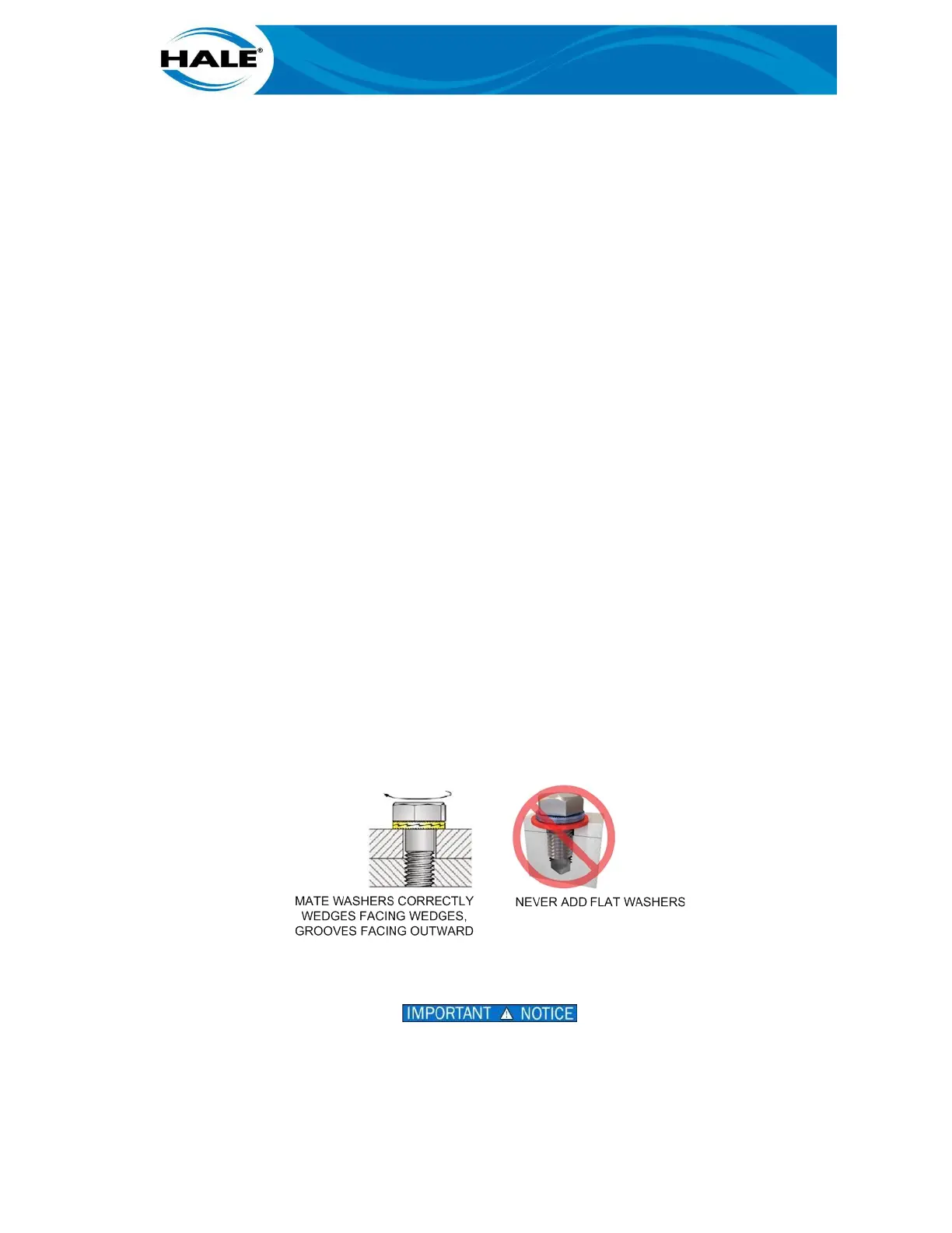
F. Install NORD-lock washers. (See Figure 32.)
Figure 33. NORD-lock Washers Installation Details
G. Install impeller nut.
DO NOT APPLY LOCTITE TO A SELF-LOCKING NUT. DO NOT REUSE A SELF-LOCKING
NUT. REUSING A SELF-LOCKING NUT OR ADDING LOCTITE MAY RESULT IN THE ITEM
FAILING TO BE SECURED.