11
2.4.1.7 PM Relief Valve Control
The PM indicates a panel mounted hand-adjustable valve. When set to the desired pressure, the
relief valve will maintain the desired pump discharge pressure and limit a pressure increase to
no more than 30 psi (2 bar).
2.4.1.8 Volute
The increasing discharge path of the pump, its function is to collect the water from the impeller
and depending on its design can either increase pressure and decrease velocity or increase ve-
locity and decrease pressure.
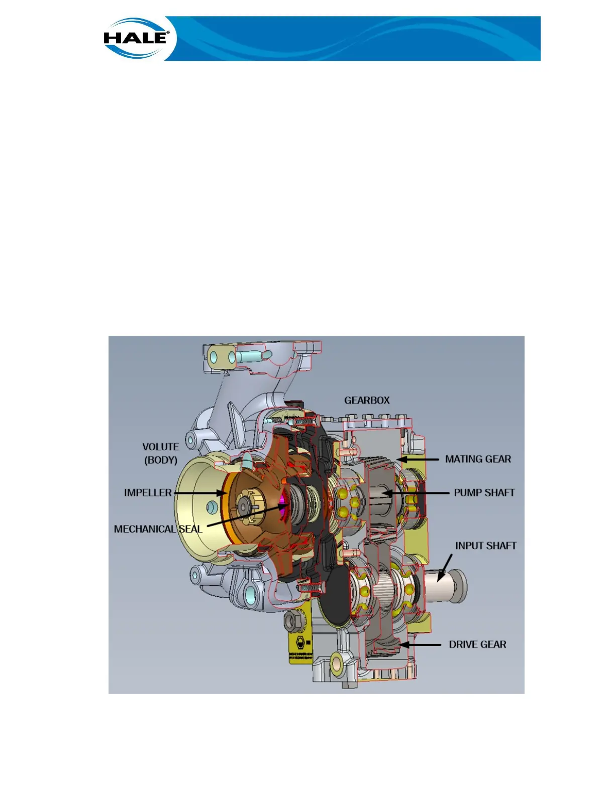
2.4.2 Standard Booster Pump Components
All Hale Flex Series single stage booster pumps (AKA the standard pump) consist of the following:
• Volute • Gearbox
•
Impeller •
Gears (Drive, Mating/Pump)
• Mechanical Seal • Shaft Assemblies (Input, Pump)
Figure 3 shows these standard parts of a Hale booster pump. These parts are briefly described in
the following paragraphs.
Figure 4. Parts Of The Hale Booster Pump