117
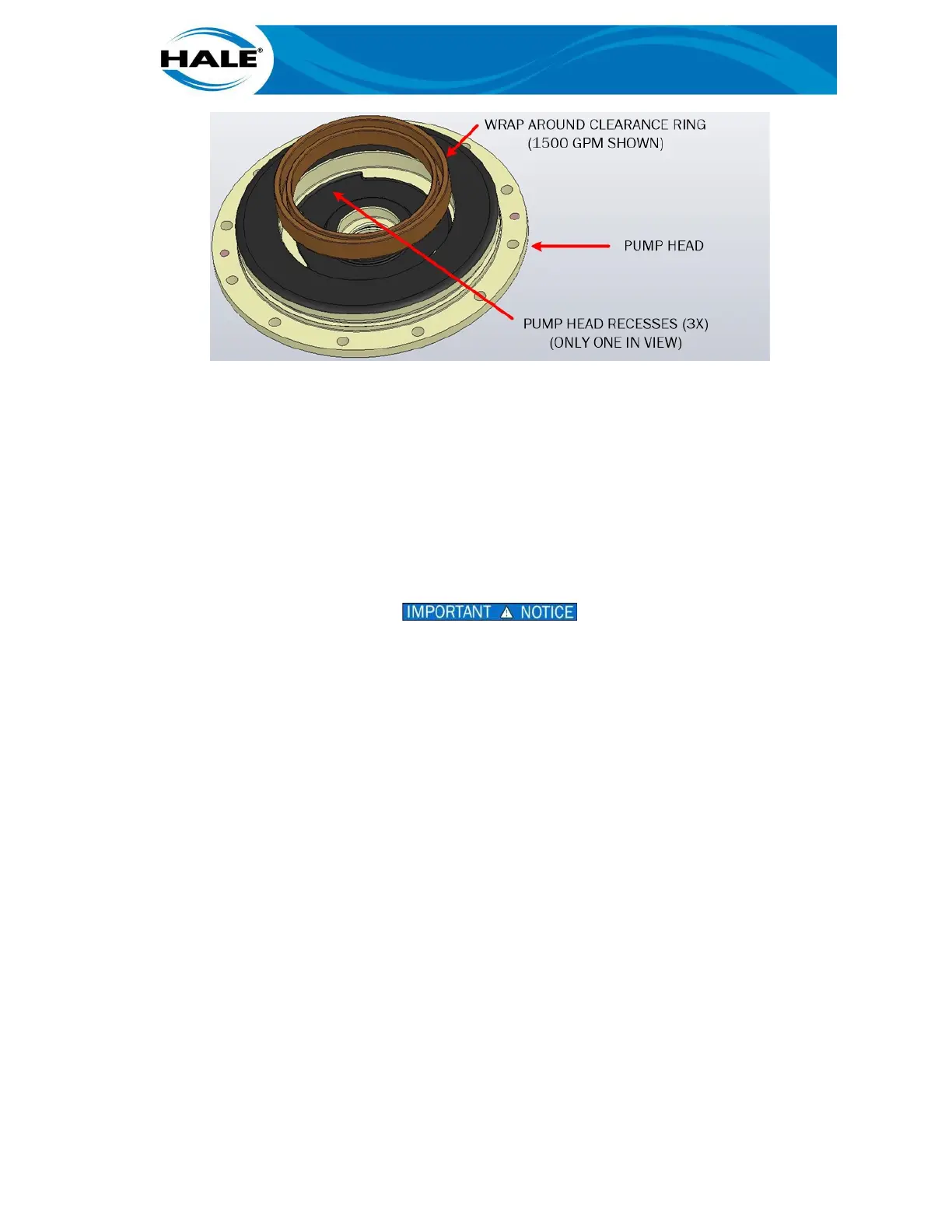
Figure 47. RSD Wrap Around Clearance Ring R & R
C. Apply force to pry bars (two-at-a-time works best) to remove clearance ring.
RSD Pump Head Clearance Ring Installation
A. Clean pump head to remove old Loctite. (Use Loctite Clean-Up Solvent and a
wire brush.)
B. Place suction head on stable work surface with suction opening down.
C. Coat ONLY outer mating surface of new clearance ring with Loctite 680.
D. Align new clearance ring to suction head.
DO NOT DRIVE THE CLEARANCE RING INTO THE SUCTION HEAD AT AN ANGLE OR
UNEVENLY (ALL THE WAY FROM ONE SIDE AT A TIME). BENDING, WARPING, OR
CHIPPING THE CLEARANCE RING MAY RESULT IN POOR PERFORMANCE OR PUMP
FAILURE.
NOTE
A circular piece of plate steel the size of the outside diameter of the clearance ring
may be used to prevent the ring from tipping or jamming inside the suction head.
E. Using hydraulic press, install clearance ring into suction head.
F. Apply a heavy coating of grease to clearance ring.
NOTE
The grease protects the clearance ring during the initial pump priming to prevent the
ring from contacting the impeller.
5.8.8 General Install On The Apparatus
After completing repairs and/or maintenance, install the pump and gearbox assembly (unit) on
the apparatus.
A. Prepare unit for installation.
Verify magnetic oil drain plug installed. 1.
Verify gearbox filled with fluid. (See paragraph 4.4.6.1 on page 42.) 2.
Attach an appropriated rated lifting device and rigging (or jack). 3.