133
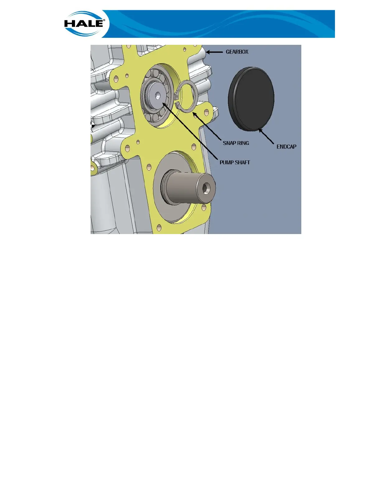
Figure 48. Pump Shaft Assembly
C. Remove pump shaft assembly.
Using a hydraulic press (a large arbor press may work), press pump shaft 1.
assembly out of drive side bearing and gearbox as follows.
NOTES
If the pump head studs are in place the bolster plate bore diameter should be at
least 6.25-in (~16 cm). If the studs and the breather/oil fill (including the elbow) are
removed, the plate bore can be 3.75 in (9.5 cm) or larger. The bore will allow the
pump shaft seal and bearing to pass thru the plate while supporting the gearbox.
If using cribbing to support/suspend the gearbox above the bolster plate the gearbox
is required to be held securely, safely, and stable enough to press the shaft out of the
drive side bearing (an interference fit) and gearbox (multiple slip fits). Using cribbing
for the shaft removal requires approximately six (6) to nine (9) inches of clearance
between the gearbox and the bolster plate. (Pump shaft travel varies depending on
pump model.)
a) Configure hydraulic press bolster plate with opening/bore hole or cribbing per
NOTES above.
b) Place gearbox (pump shaft side down) on bolster plate (or cribbing) so gearbox is
stable and secure and pump shaft assembly will pass thru plate opening or crib-
bing.