101
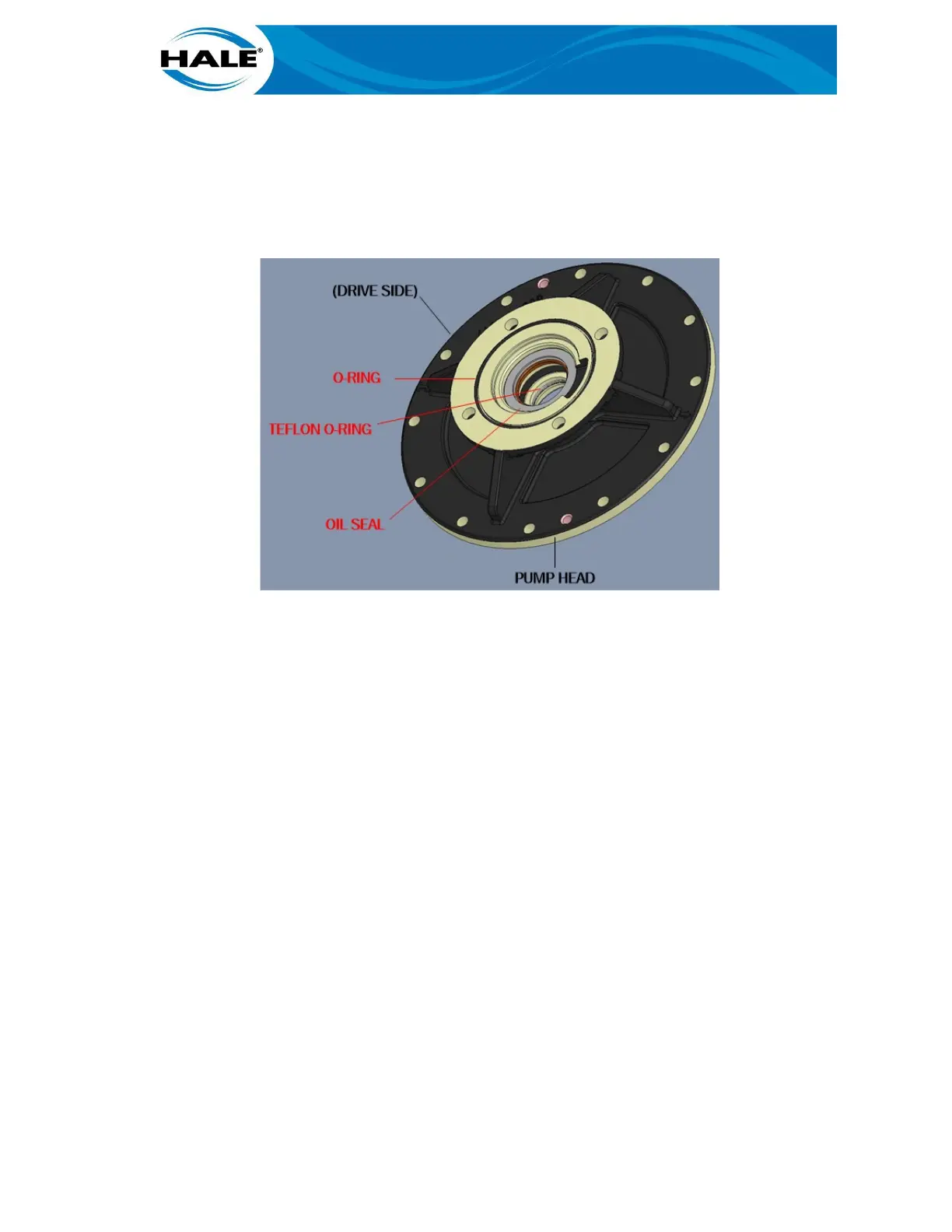
a) Lubricate new O-ring (gearbox to pump head). Refer to Table 20.
b) Install new O-ring on pump head.
c) Lightly lubricate (grease) mating surface of new oil seal (and pump head bore).
(Refer to paragraph 5.7.2 on page 49).
d) Install new oil seal in pump head.
Figure 38. Pump Head (Drive Side)
B. Install pump head on gearbox, do not damage oil seal or pump shaft.
NOTE
Unless the match marks differ, position weep holes at 12 and 6 o-clock with respect
to vertical for installation of pump in the apparatus regardless of gearbox position
used (Left, Right, or Down position is allowed).
C. Clean original fastener threads (or replace with correct new fasteners). Then
apply Loctite™ 243 (or equivalent) to threads.
D. Secure pump head to gearbox.
Install four washers. 1.
Install four (4) M12 x 1.75 full nuts. 2.
Using a 3/4-in (19 mm) wrench tighten (CW) four (4) M12 x 1.75 full nuts. 3.
E. Using a cross pattern, torque nuts. Refer to Table 22 for recommended
torque values for fastener size and material.
With only the pump head installed, use the instructions in paragraph 5.8.4.10, RSD Mechanical
Seal R&R, and paragraph 5.8.4.10, RSD Impeller R&R, to install the seal and impeller. Then refer
to paragraph 5.8.4.5 for instructions to install the inducer and install the volute as described in
5.8.4.2, RSD Volute R&R. Finally, install the suction head and test the pump as described in par-
agraph, 5.8.4.1, RSD Suction Head R&R.