25
Subject to change without notice
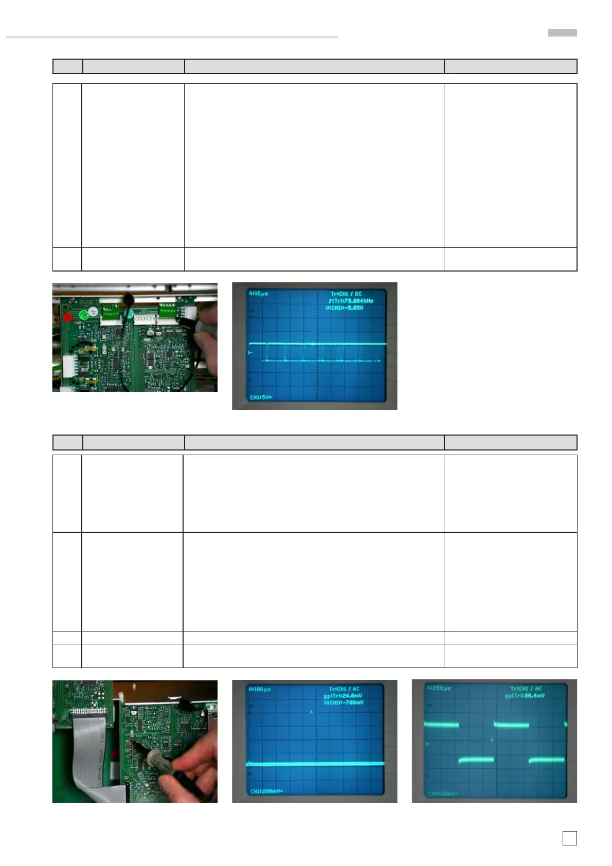
6.4 Use an oscilloscope and measure the control voltage D_ANA at pin
1 of Molex connector J4801 (located on MB board) connecting YF
and MB board.
If the voltage is constantly -6 V= , although analog mode is chosen,
the YF amplifi er is constantly set to digital mode and the MB board
generates the wrong level. Continue with item 6.5.
Note
In analog mode the following conditions should appear:
0 V constantly = Readout is switched off.
Pulses from 0 V (analog signal) to -6 V (readout insert in digital
condition) with readout on.
In digital mode -6 V should always be present.
See photo C6.4.1.
See photo C6.4.2
6.5 Change the MB board and adjust item 37 – 45, 57 – 61 and 63 - 64
as described in the Adjustment Procedure.
Item Instrument Behavior What to do Remark
7.1 Digital mode:
No trace visible in digital
Dual and Single Channel
mode, readout is dis-
played.
Press AUTOSET pushbutton.
If no trace is displayed continue with item 7.2.
Note:
As the readout is displayed the
signal, the display section - con-
sisting of MC board with the D/A
conversion and the Y- and X-Final
Amplifi er - cannot be the reason
for the error.
7.2 Apply the 1 kHz calibrator signal of the oscilloscope via a *10 probe
to the input of channel 1 and operate the oscilloscope in channel
1 mode.
Switch over to Analog mode and press AUTOSET to get a suitable
signal display. If the signal is not displayed with 4 cm height, set the
channel 1 VOLTS/DIV control to 5 mV/cm.
Return to digital mode and continue with item 7.3.
7.3 Locate and identify pin 7 at J2602 on YP board
See photo 7.3.
7.4 Connect a *10 probe with pin 7 at J2602 and measure in combination
with DC and AC coupling. Continue with item 7.5
See photo 7.4.1 DC and 7.4.2 AC
Item Instrument Behavior What to do Remark
photo C6.4.1
photo C6.4.2
photo C7.3
photo 7.4.2
photo C7.4.1
HM1508-2 Troubleshooting

 Loading...


