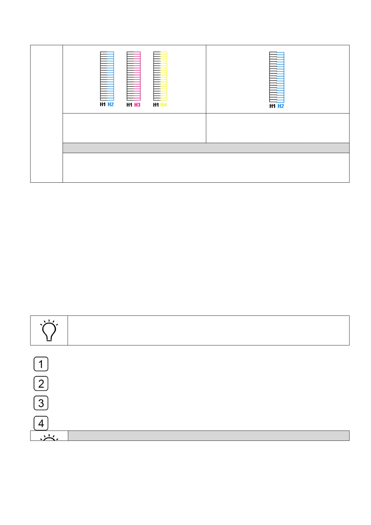
H2, H3 and H4 are aligned to H1.
Horizontal calibration is good.
H2 is not aligned to H1.
Adjust the screw clockwise to make it
aligned to the left black head.
How to adjust the Horizontal Adjusting Screw
1. Loosen the Head Fixing Screw
2. Adjust the Horizontal Adjusting Screw according to the Vertical calibration print.
3. Fasten the Head Fixing Screw when the vertical alignment accomplished.
4.11.3 Left/Right heads offset
“Left-dir heads offset” means color calibration of left-directional print.
“Right-dir heads offset” means color calibration of right-directional print.
Select the “Left-dir Heads Offset” in the drop-down-list of calibration and alignment,
print the checking icons as the sample shown below.
Use the magnifier to observe the best alignment of the offset calibration print and take
it as a variable to adjust the original value.
Modify the value with a variable in the corresponding blank of “Color Module
Calibration” sector and check the alignment again.
Repeat Step1, Step2 and Step3 until they were aligned.
How to read the Left/Right Offset Calibration print