73
Before starting Installation
Operation
Screen block
diagram
Function setting Program System setting Specifications
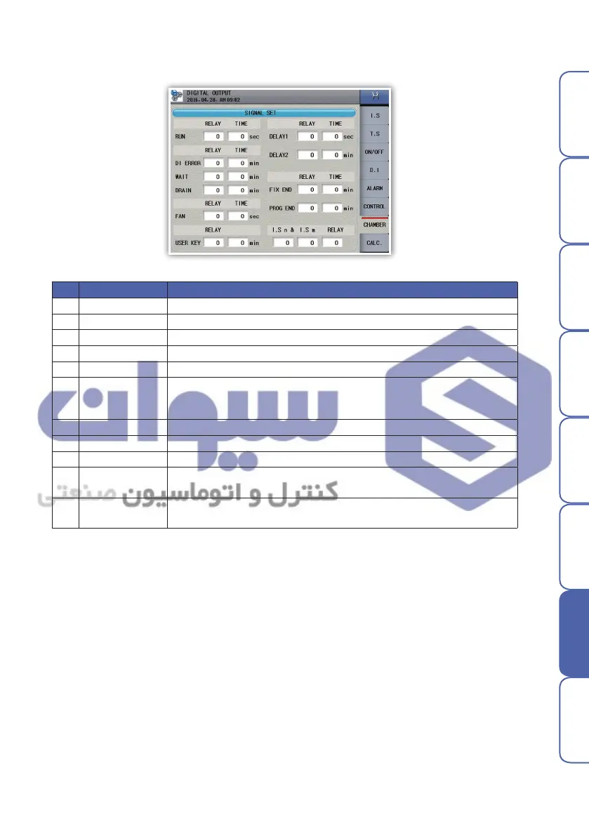
- Operator can set relay of signals relating to operation
▶ Chamber signal
No. Name Description
1 Running
Setting relay and delay time of running signal. After delay time, relay start operating
2 DI
Setting relay and holding time of DI signal. During the holding time, relay operating
3 Wait
Setting relay and holding time of wait signal. During the holding time, relay operating
4 Drain
Setting relay and time of drain signal. During the holding time, relay operating
5 FAN
Setting relay and time of FAN signal. Relay activates upon the equipment running, relay
6 User Key
Setting relay and delay time of user button. If you activate the button
window in the operation screen it is possible to operate the user button
arbitrarily.
7 Delay 1
After the IS1 output, correspondent relay operating after the delay during the set time(Sec).
8 Delay 2
After the IS1 output, correspondent relay operating after the delay during the set time(Min.)
9 Fixed running
If the fix operation turns off, correspondent relay operating during the set time
10
Programming
running
If the program operation turns off, correspondent relay operating during the set time
11 IS complexion
Set the IS number and relay linked to the IS1. If the IS1 and linked IS number
turn ON correspondent relay operating
Fig. 115) DO-Chamber signal
هﺮﮐ ﮓﻧﺎﯿﻧﺎﻫ تﻻﻮﺼﺤﻣ یرﺎﺼﺤﻧا هﺪﻨﯾﺎ ناﻮﯿﺳ ﺖﮐﴍ
 Loading...