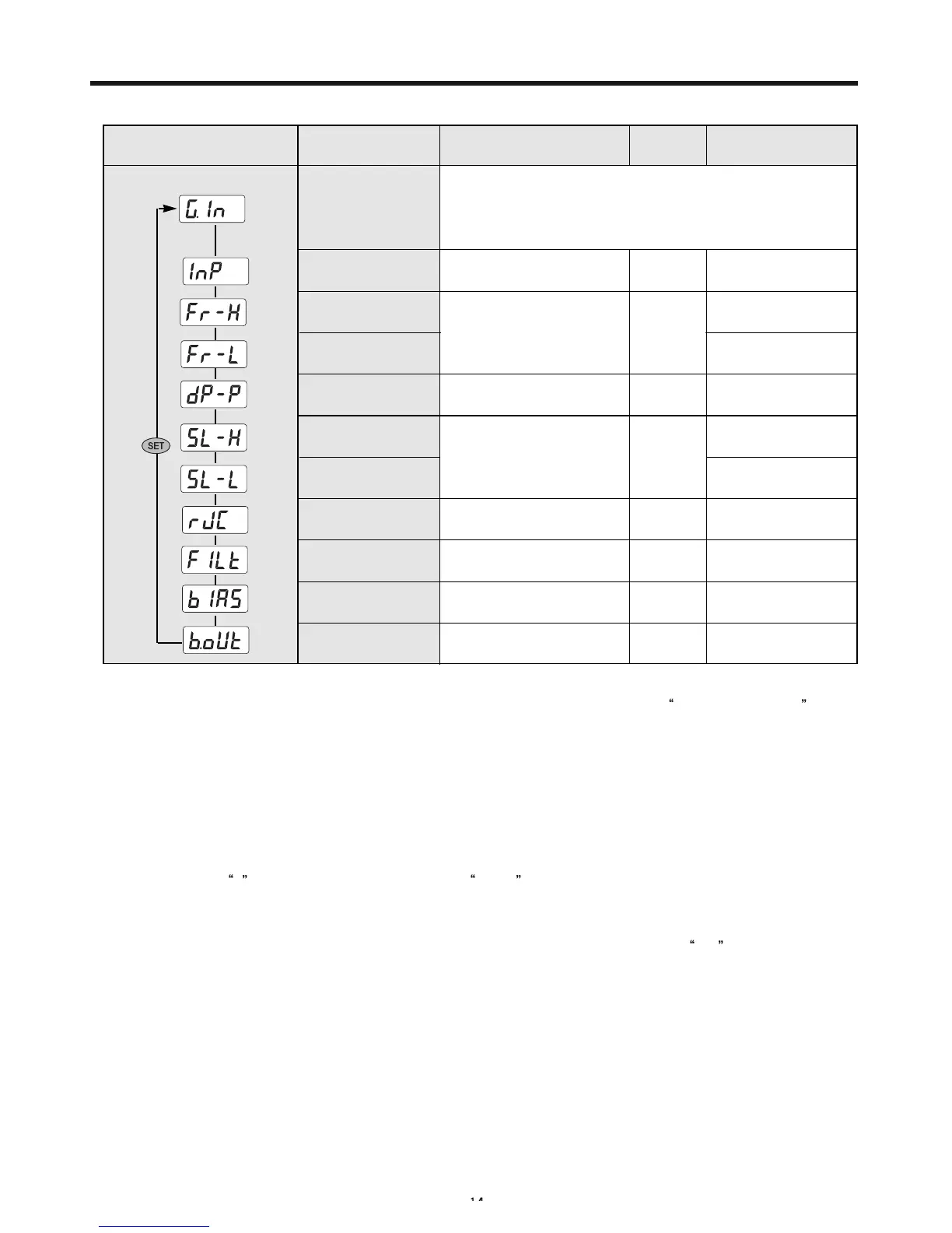
8-1-1. Input Setup group
Refer to Input type and
measurement range
Setup range
Display
condition
Initial value
Input group
Input type
selection
Max. limit selection
Min. limit selection
Decimal point
position
Max. scale setup
Min. scale setup
Temperature
compensation
PV filter
PV bias
Burn-out
Refer to Input type and
measurement range
(FR-H > FR-L)
0~3
-1999~9999
(SL-H > SL-L)
ON , OFF
OFF , 1~120
-100~100 %(EUS)
OFF , UP ,DOWN
Always
Always
In Voltage
input
In Voltage
input
TC
Always
Always
1370
-200
1
100.0
K(1)
0.0
ON
OFF
0 %
UP
Item
NP100
1) Selection of Input Type: NP100 Program Temperature Controller supports universal input and can be
conveniently used by selecting and setting up the input signal symbol of the
Input Type Range List.
This list includes the application input sensor and input types in accordance with voltage among the
total of 18 types of input such as 12 types of thermocouple input (13 types of range), 2 types of R. T. D
input, and 4 types of direct current voltage input.
2) Selection of Maximum and Minimum Range: Select the maximum and minimum value of the range
within the maximum range for the setup item in changing the range.
3) Setup of Decimal Point Position: When selecting voltage input (V, mV) for the input type, decimal point
can be indicated by selecting the position of first through third in order to indicate process value in dec-
imals. (Select
1 to indicate one decimal place 000.0 .)
4) Selection of Maximum and Minimum Scale: Select the maximum and minimum scale when selected
voltage input (V, mV) for the input type.
5) Selection of Temperature Compensation: As for the thermocouple input, select
ON for the selection
of temperature compensation to compensate voltage for the terminal temperature. Otherwise, it will
show declination as much as the terminal temperature (surrounding temperature).
6) Selection of Process Value Filter: When instability of the measurement value for the digital instrument is
severe due to the external noise, reduce the instability of the process value by selecting the filter value.
7) Selection of Process Value Bias: Select correction value when it is necessary to correct the process
value due to the error in input sensor.
8) Selection of Burn-Out Operation: As the safety mode of output in OFF condition by ordering the maxi-
mum or minimum value and comparing with the set value when input (sensor) is disconnected, maxi-
mum process value is indicated if UP is selected and minimum is indicated when DOWN is selected,
thus output remains in OFF condition.
Setup below items.
Always
Signal
 Loading...