NP100
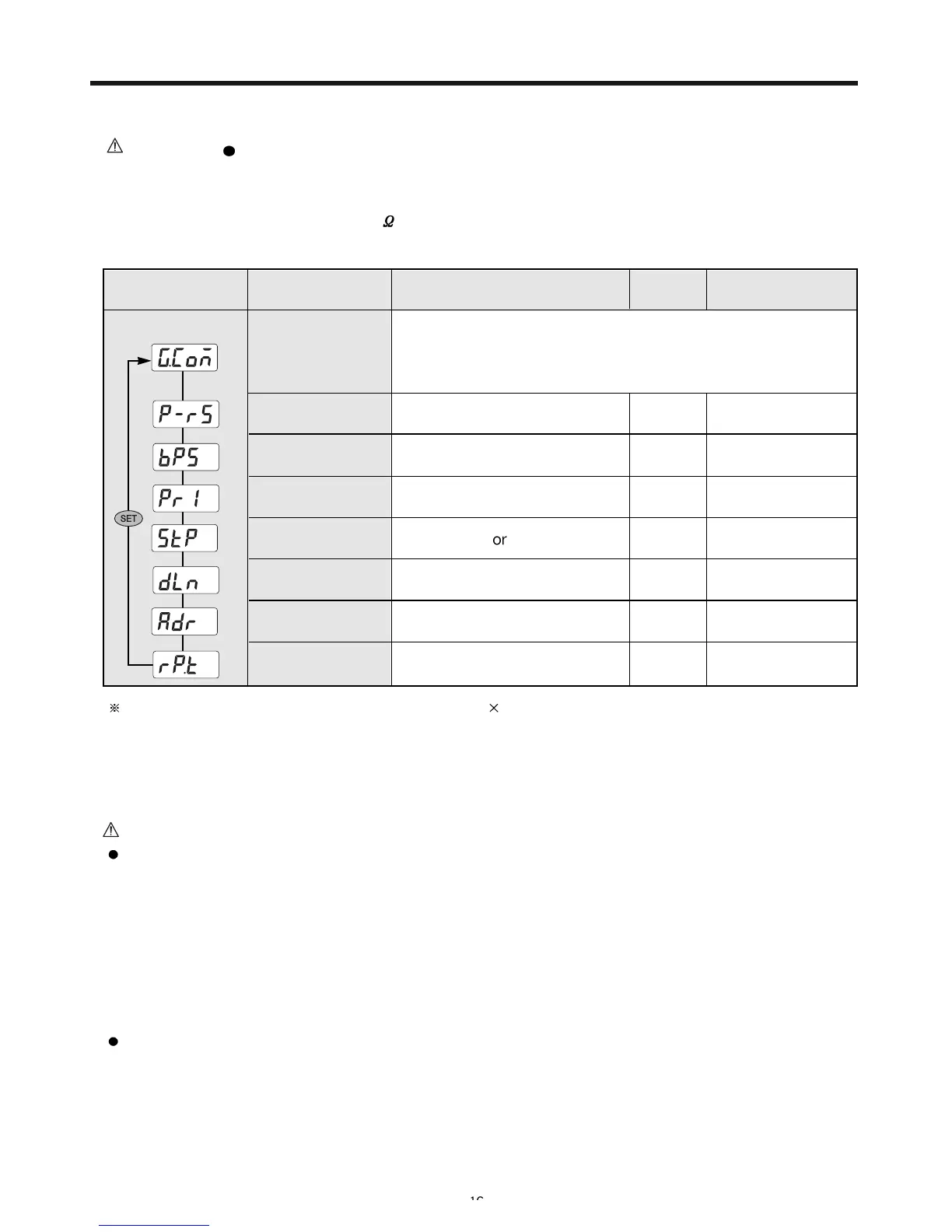
8-1-3. Communication Setup Group
Signal
Setup range
Display
condition
Initial value
Communication
setup group
1
2 bit
7 or 8
(except PC Link : 8)
1~99(max. 31 devices)
0~10
Option
Option
Option
Option
Option
Option
Option
NONE
1
8
1
PCL.0
0
Protocal
selection
Communication
rate
PARITY
STOP BIT
PCL.0: PC LINK
PCL.1: PC LINK SUM
Item
DATA LENGTH
ADDRESS
RESPONSE TIME
600 / 1200 / 2400
/ 4800 / 9600 bps
NONE / EVEN / ODD
9600
Setup below items.
8-1-4. Retransmission Setup Group
Response time = (handling time + response time) 10 ms
Caution
Retransmission Output Wiring
- Must disconnect the controller and external power source when setting up/removing a receiver since
there is danger of electric shock.
- Use same terminal for retransmission output and SPS output. Use of the terminal with what function of
output is selected through parameter.
- 4/20m ADC is outputted for the retransmission output.
- When using the retransmission output, it is impossible to use the SPS function for sensor.
SPS Output Wiring for Sensor
- Must disconnect the controller and external power source when setting up/removing a sensor since
there is danger of electric shock.
- Same terminal is used for the SPS output and the previous retransmission output. Using the terminal as
an output of one side is selected by the parameter. (24 VDC 20mA DC MAX)
Caution! PC-LINK Communication / LADER Communication Wiring
- Must disconnect the controller and the external power source when connecting to the communication
terminal due to the danger of electric shock.
- Connect the termination resistor (220
1/4W) at the end or master located at the both ends of the
communication equipment.
 Loading...