3 - Description
3.8
DANGER! Never open the Cyclone filter unless the top green
pressure manifold valve and bottom black suction manifold
valve are both closed (turned to the unused position).
Otherwise, spraying liquid could hit you when opening the
filter, and drain from the tank!
With the CycloneFilter, the impurities that exist in the spray liquid
will by-pass the filter and be recirculated back to the tank via the
return flow.
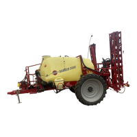
Function diagram
1. Filter lid
2. From pump
3. To boom
4. Return to tank
5. Return valve
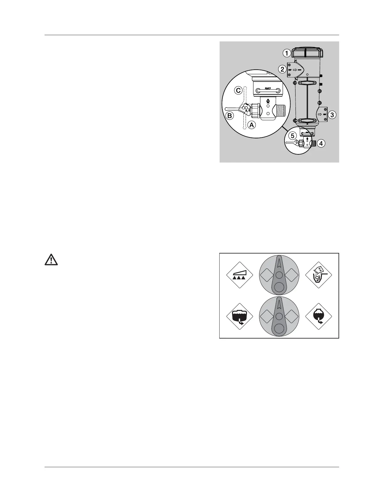
Valve (5) has three positions marked with small dots on the lever:
Position A (Marked with 1 dot): There is no return flow. Position is
used when flushing the boom if there is spray liquid in the main
tank. Also used when high spraying volume is required.
Position B (Marked with 2 dots): Normal spraying position. With
return flow to prevent clogging the filter when spraying. Position is
used when flushing the boom if the main tank is empty.
Position C (Marked with 3 dots): Flushing position, which is used if
filter is clogged. Lift and hold the lever to use this position which
largely increases return flow and cleans the filter.
See Maintenance section for service of filter.
CycloneFilter
 Loading...