AXIS4000 WHEEL ALIGNMENT SYSTEM
HAWEKA Wheel Alignment –AXIS4000
7.2.3 Interface:
After successful installation, a new virtual COM interface for
communicating with the FM transmitter is added to the com-
puter.
The interface option in the program should be set to AUTO for
automatic connection.
The interface can be manually changed to a selected port only
when necessary (no connection to the cameras).
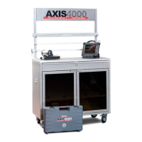
A new entry with the new COM interface for the FM
transmitter is added in the device manager under
Windows.
(Fig. 11)
Radio channel:
The radio channel set in the cameras is automatically shown for data transfer between camera sen-
sors and program.
If required, the radio channel in the cameras can be changed and must then be accepted by the
program using the Magnifier button.
Magnifier button
The dialogue window is split into two areas. The cameras found by the program but not yet connect-
ed are shown in the left area. The right area shows the camera(s) that is(/are) already connected
wirelessly to the program.
The cameras and FM transmitter must be set to the same radio channel.
Serial numbers:
The camera serial numbers are displayed as soon as the program has established a connection to
the camera.
7.2.4 Camera symbol information:
The camera connection and charge level of the batteries is continually monitored and displayed
throughout the entire program run-time.
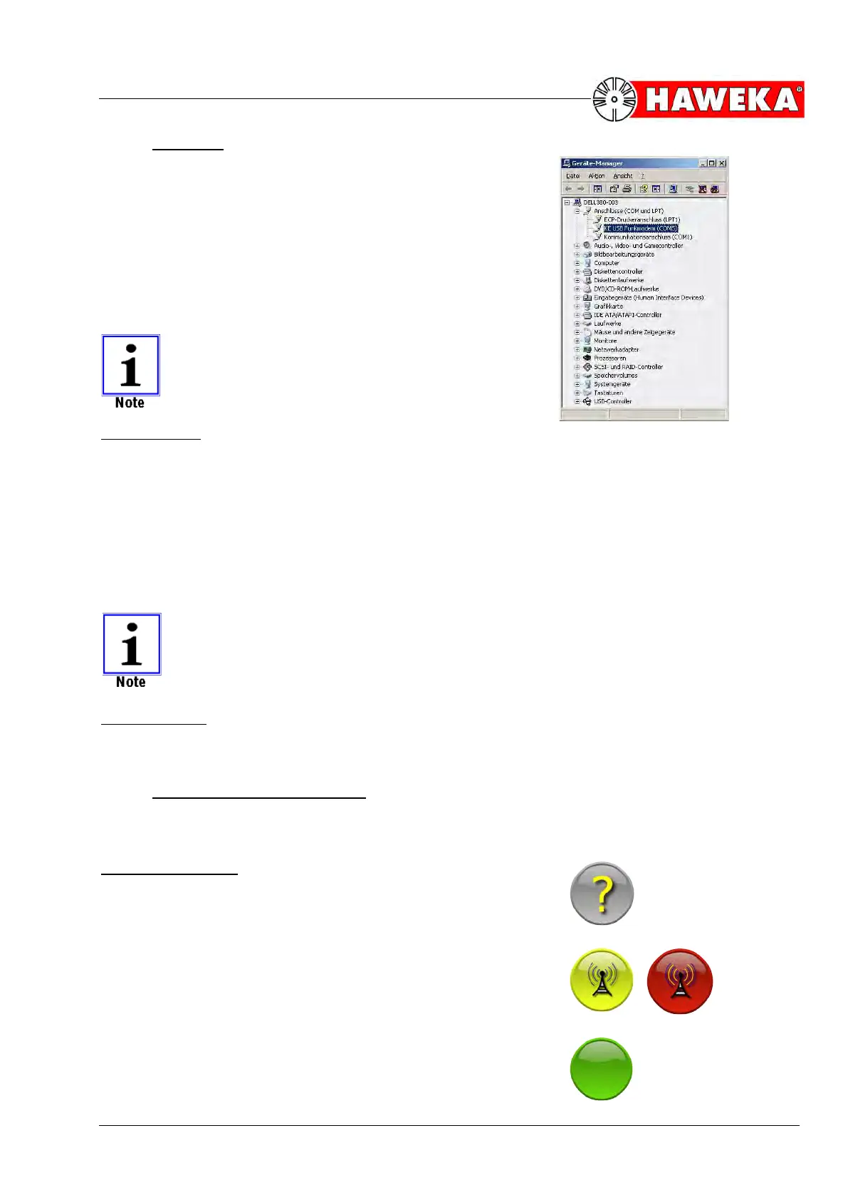
Symbol description:
The program has not yet polled a connection to the camera; sta-
tus unknown.
(Fig. 12)
The display flashes between yellow and red. The program is at-
tempting to connect with the cameras.
(Fig. 13)
Display is green: a connection is established to the camera.
(Fig. 14)