AXIS4000 WHEEL ALIGNMENT SYSTEM
HAWEKA Wheel Alignment –AXIS4000
Front axle measurement
9.2 Specifying vehicle data in the AXIS4000 program
The Radio Server Unit is connected to the PC (see Installation Point 6.4) and the PC is switched on.
The AXIS4000 program has been started and is showing the start screen.
• Select the Start measurement button.
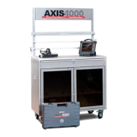
• Enter vehicle data and select the vehicle type using
the quick selection function.
(Fig. 29)
The quick selection function enables the user
to directly accept preset vehicle values. How-
ever, specific changes can be made depend-
ing on the vehicle type.
• The Special vehicle option is used to set up an indi-
vidual vehicle of up to 5 axles for measurement.
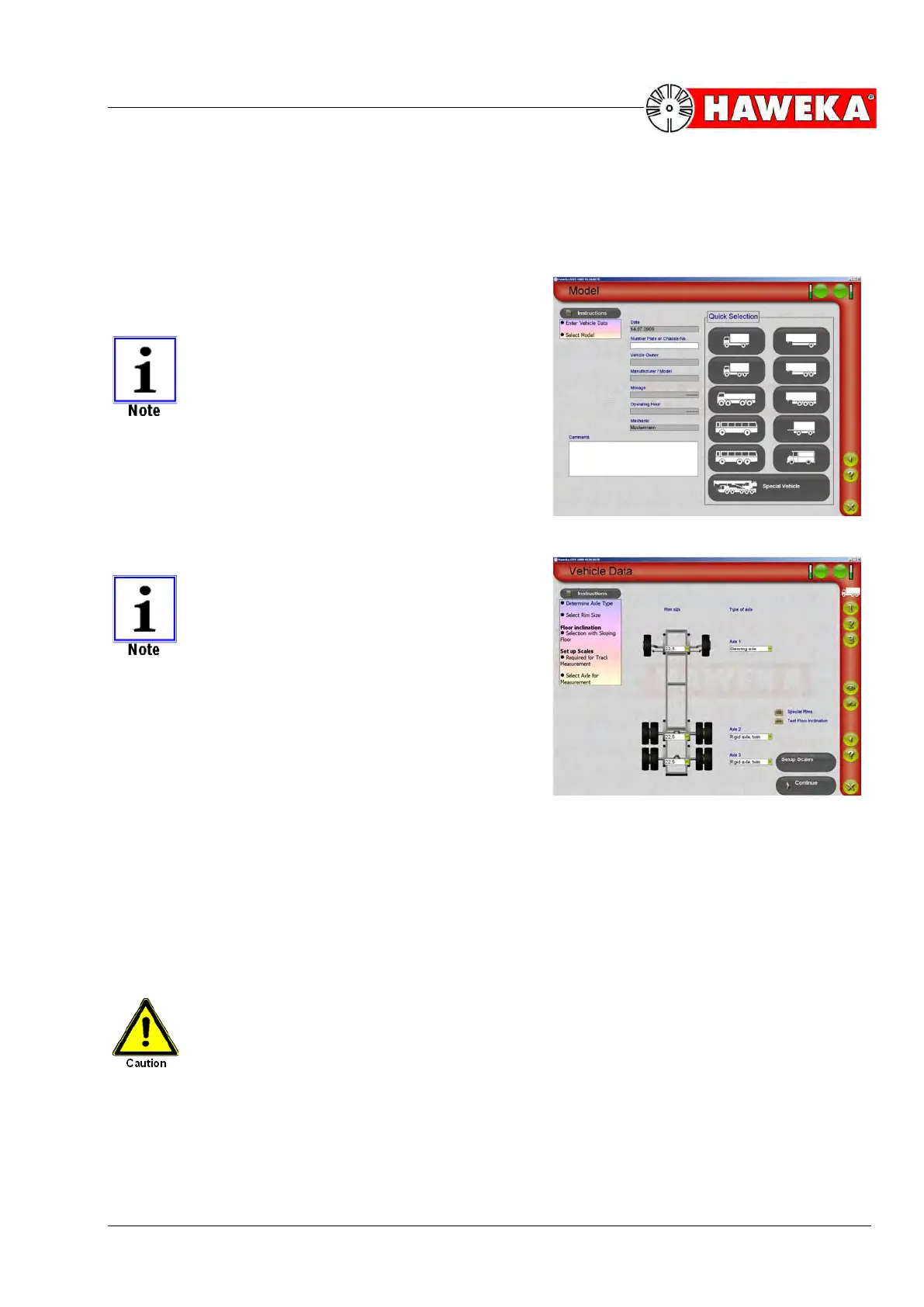
• Define the rim size on the following "Vehicle data"
program screen and specify the type of axles de-
pending on the vehicle.
(Fig. 30)
• Now select the Setup scales button.
Using the Continue button, skip the scale
setup and go straight to selecting the meas-
urement types.
(See Page 32)
This option is only used for quick measure-
ment of camber, castor, KPI, relative steering
angle and max. steering angle.
All other measurements can only be carried
out when scale setup has been carried out be-
forehand!
• Select Test floor inclination
The vehicle must be measured on a level floor surface. If the user suspects that the selected
work surface is not on a horizontal plane between left and right vehicle sides, the situation
should be examined and taken into account for further measurements. This step is not abso-
lutely essential but is recommended in the event of any suspected floor surface inclina-
tion. On this subject, please refer to Point 14 from Page 52
• Select Special rims
In some rare cases, you may not be able to position the wheel alignment clamp for the cameras
correctly on the rim.
The camera measurement head must always be aligned parallel to the wheel hub.
In the case of Trilex rims, we cannot guarantee correcting positioning of the wheel alignment clamp
due to the 3-part composition of the rim. Depending on the vehicle wheel, run-out compensation for
the individual camera measurement heads must be carried out using the Special rims button. On
this subject, please refer to Point 15 from Page 54.