AXIS4000 WHEEL ALIGNMENT SYSTEM
HAWEKA Wheel Alignment –AXIS4000
Front axle measurement
9.3 Setting up the reflectors (scale setup)
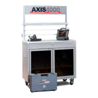
9.3.1 Fitting the magnetic feet onto the vehicle
• Secure the magnetic feet onto the vehicle chassis as central-
ly as possible.
• Make sure that the magnetic feet are fitted at the same point
on both sides of the vehicle.
(Fig. 31)
• Attach the reflectors onto the magnetic feet at the same posi-
tion on both sides.
The magnetic feet should be fitted to the vehicle
chassis as far away from the cameras as possible.
This creates a larger measurement rectangle.
• When the magnetic feet with reflectors are secured
to the vehicle, the left and right cameras must be
aligned to the reflectors.
When a camera detects a reflector, the symbol top
right in the program changes and the process is con-
firmed by pressing the OK button on the corre-
sponding camera.
• The program signals receipt of the measured values
both visually with a green OK symbol and acoustical-
ly with a signal tone.
• It does not matter in which sequence (left/right) the
reflectors are detected and confirmed by the OK but-
ton for the corresponding camera.
(Fig. 32)
• Once both reflectors have been detected and cali-
brated, the program changes automatically to reflec-
tor stand setup.
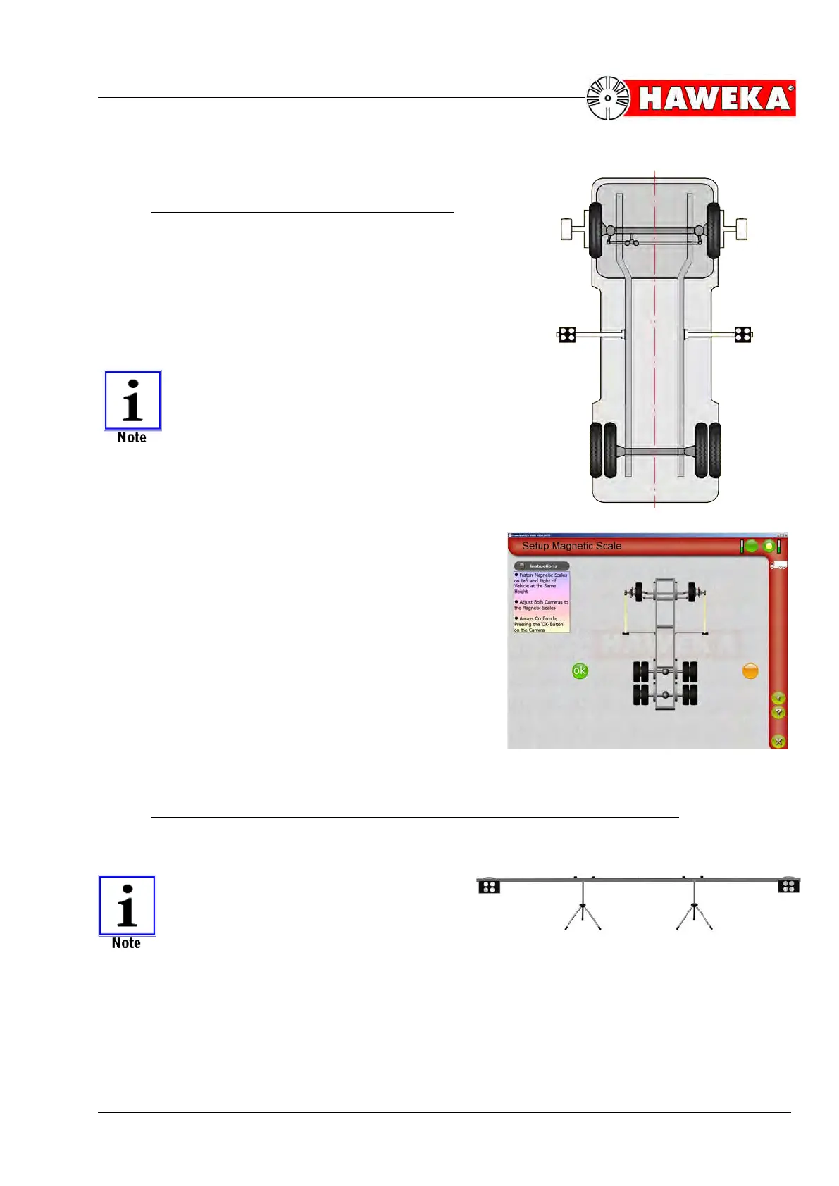
9.3.2 Assembling the reflector stands (toe scales) and aligning to the vehicle
There are 2 reflector stands each with 2 reflectors.
THE REFLECTORS ON THE MAGNETIC
FEET ARE REMOVED TO SETUP THE
REFLECTOR STAND.
• Assembly is carried out by putting together the reflec-
tor stand, tripod stands and reflectors.