AXIS4000 WHEEL ALIGNMENT SYSTEM
HAWEKA Wheel Alignment –AXIS4000
9 Front axle measurement
9.1 Preparatory measures on the vehicle
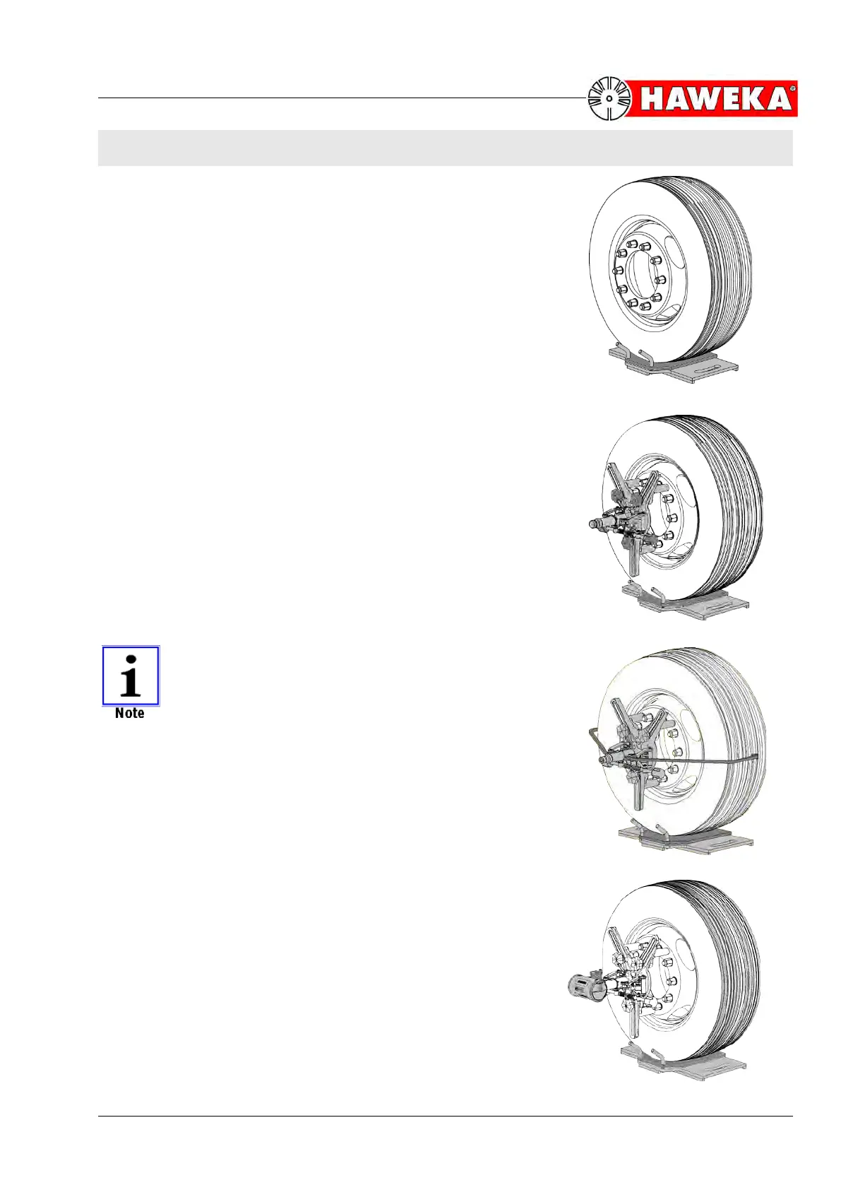
Driving the vehicle onto the turning plates
• Place the turning plates centrally on the left and right in front of
the front wheels.
• Use the bolts to secure the plates against moving.
• Drive the vehicle onto the turning plates. The centre-line of the
wheel must be aligned over the centre of the turning plate.
(Fig. 25)
• Remove the securing bolts from the turning plates.
Fitting the camera measurement heads
• Adjust the magnetic feet on the 3-arm star to the required rim
flange.
• The excentres must be adjusted to ensure full-surface contact
on the rim flange between the wheel nuts and to ensure that all
3 magnetic feet are the same distance from the centre of the
stand.
• Place the measurement heads with the magnets onto the
cleaned rim flange. There should be two magnets above the
wheel centre and one below.
(Fig. 26)
MAKE SURE THAT THE MEASUREMENT HEADS
AND CAMERA SHAFTS ARE EACH FITTED CEN-
TRALLY IN LINE WITH THE CENTRAL HOLE OF THE
RIM.
In the case of aluminium rims, the two grab arms must each be
screwed onto the wheel alignment clamp. The wheel alignment
clamp is attached centrally to the wheel. The magnetic feet are
placed against the rim flange, and the grab arms are wedged into
the tyre profile using the quick-tensioning device.
(Fig. 27)
Mounting the cameras
• Pull the attachment bolt of the camera up slightly, and push the
camera onto the camera shaft until it clicks into the groove on
the shaft.
• Now lock the camera onto the shaft by gently tightening the
attachment bolt.
(Fig. 28)