AXIS4000 WHEEL ALIGNMENT SYSTEM
HAWEKA Wheel Alignment –AXIS4000
Front axle measurement
9.4 Measuring the camber
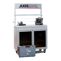
• Before beginning measurement, align the cameras
horizontally using a spirit level.
(Fig. 37)
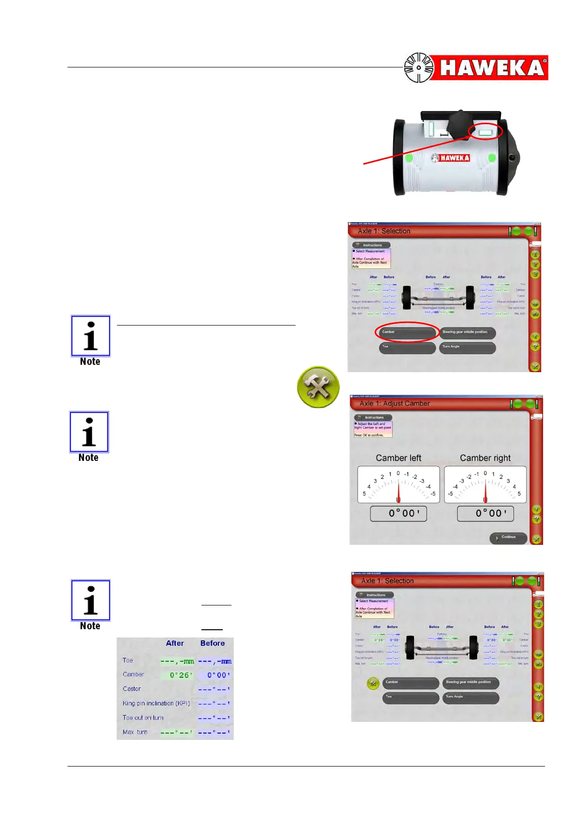
• Select the "Camber" button on the measurement
selection screen for measuring the ACTUAL camber
value. The camber value will then appear immedi-
ately in degrees and minutes.
(Fig. 38)
• The measured ACTUAL values must now be com-
pared to the required NOMINAL values.
• If the ACTUAL values lie outside the tolerance
range of the NOMINAL values, then the camber
must be adjusted on the vehicle when possible.
The following applies for adjustments:
IF THE CAMBER IS ADJUSTABLE ON
THE VEHICLE, THEN THIS IS ALWAYS
ADJUSTED FIRST.
• Click on the settings symbol to adjust the
camber.
THE SETTINGS SYMBOL ONLY AP-
PEARS AFTER MEASURING THE ACTU-
AL VALUE.
• While carrying out settings, the current value for the
left and right sides of the vehicle is displayed ana-
logue and digital for setting the NOMINAL value.
(Fig. 39)
• The Continue button changes the program back to
the overview screen for the selected axle and dis-
plays the newly set value in the AFTER column.
(Fig. 40)
The BEFORE column means
measured values before the setting.
The AFTER column means:
measured values after the setting