AXIS4000 WHEEL ALIGNMENT SYSTEM
HAWEKA Wheel Alignment –AXIS4000
Rear axle measurement
10.2 Toe / inclination
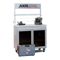
• To measure the ACTUAL value, the cameras are
turned to the front reflectors and back reflectors and
the measured values for each are recorded with the
OK button. The individual work steps are described
by instructions in the program window.
(Fig. 68)
• The Continue button changes the program back to
the overview screen for the selected axle and dis-
plays the measured values in the BEFORE column.
If axle inclination and/or axle mismatch are identified
during measurement, the result will be shown graphically
in the program.
(Fig. 69)
The axle inclination is shown graphically in
the program only from a value of > 0°12'
and axle mismatch is shown with a green
arrow upwards of > 1 mm and a red arrow
upwards of 10 mm.
To adjust the toe and inclination, click the adjust symbol
next to the selection button.
• Select the corresponding item for adjustment depend-
ing on the measurement result and vehicle axle.
(Fig. 70)
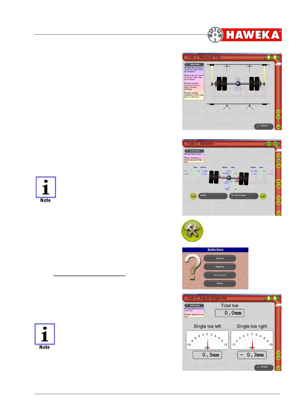
10.2.1 Adjusting the toe/single toe
• One (total toe) or two displays for single toe values
for the left and right sides are shown for adjusting
the NOMINAL value. The current values and total
toe are displayed analogue and digital in [mm] for
the entire duration of adjustment.
(Fig. 71)
If the toe value is needed in degrees, then
the display can be changed from [mm] to
[degrees].
On this topic, please refer to Point 7.2.8 Ex-
tended settings.