AXIS4000 WHEEL ALIGNMENT SYSTEM
HAWEKA Wheel Alignment –AXIS4000
Trailers
13.4 Examining the trailer coupling ring in relation to the vehicle centre-line
• Fit the camera measurement heads on the left and
right of the rear vehicle axle.
• The magnetic feet remain on the vehicle chassis
and the reflectors are turned by 180 degrees and
attached again.
• Place the cameras onto the wheel alignment
clamps on each side of the vehicle and align
against the reflectors on the magnetic feet.
(Fig. 102)
• Once the reflectors have been detected, confirm
the process with the OK button on the camera.
• The program then changes screen automatically.
Now the reflector stand must be secured to the
trailer coupling ring using the adapter.
• Remove the magnetic feet from the chassis.
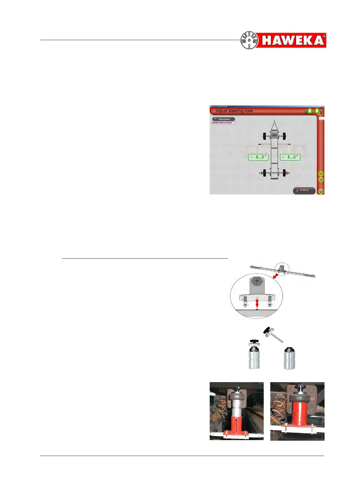
13.4.1 Attaching the reflector stand to the trailer coupling ring
• Put together the reflector stand using the king pin
adapter as described for the articulated trailer under
Point 12.2.
(Fig. 103)
• The coupling adapter is unscrewed (Fig. 104) and
pulled up from below into the trailer coupling of the
drawbar.
• Now push the knurled screw with fitting plate from
above through the trailer coupling and screw the
coupling adapter securely to the drawbar.
(Fig. 105)
• Now the king pin adapter with reflector stand is
pushed onto the coupling adapter and screwed tight
using the knurled screw.
(Fig. 106)
• The reflectors are attached to the reflector stand
on the right and left sides.