26
PME-MP85
A0897−3.4 enHBM
5 Connections
WARNING
Before starting the device, read the safety instructions.
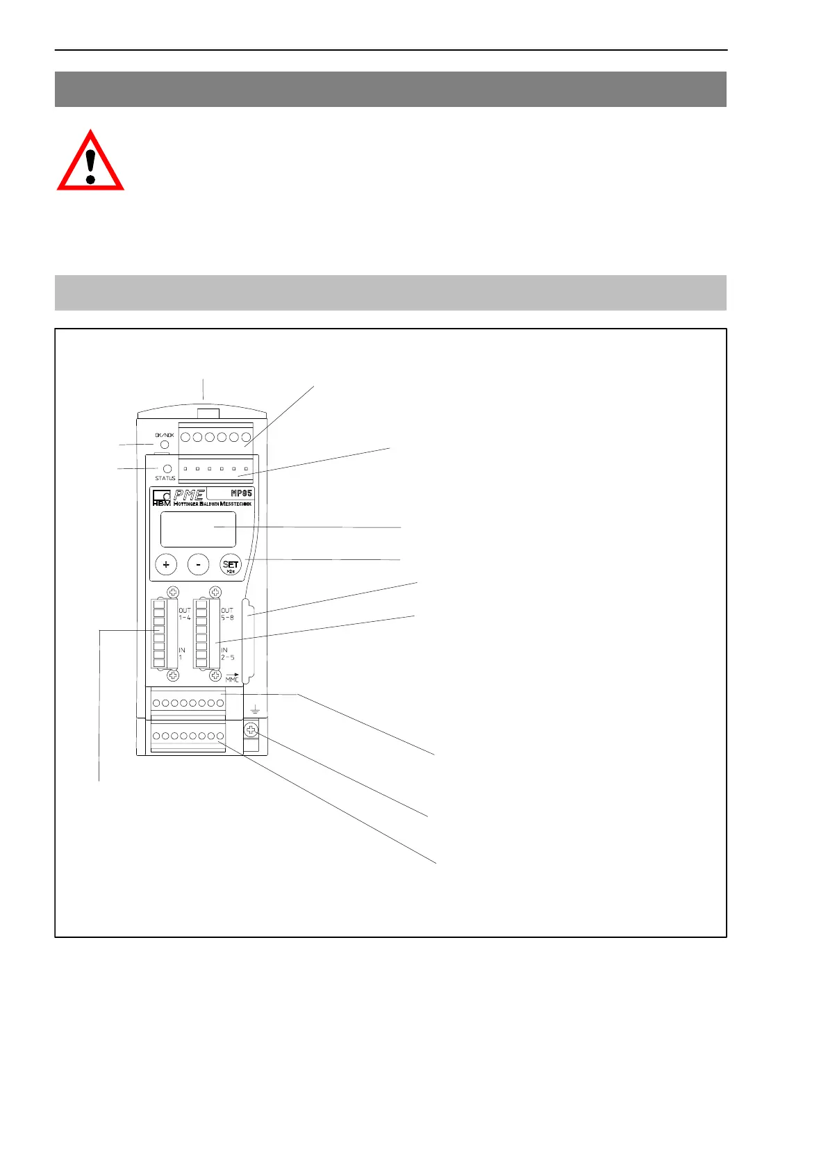
5.1 MP85 functional overview
Screw terminal 1:
Voltage supply and CAN bus, synchronization
Screw terminal 5:
Transducer connection channel x
including transducer excitation
Control keys
Two line LC display
Screw terminal 2: (same assignment as
screw terminal 1)
CAN adapter for PC/laptop connection,
parameterization via CAN bus
Screw terminal 6:
Transducer connection channel y
including transducer excitation
LED 1
Local connection of CAN bus, supply voltage and synchronization between
modules
Screw terminal 4:
4 potential-separated control inputs
(24 V level, related to input ground
screw terminal 3)
4 potential-separated control outputs
(24 V level, supply via screw terminal 3)
Screw terminal 3:
1 potential-separated control input
(24 V level) incl. input ground,
4 potential-separated control outputs
(24 V level), injection of external supply
for control outputs or incremental or
SSI encoders
Cable shield connection for
transducers
Multi Media Card (MMC) module
LED 2