28
PME-MP85
A0897−3.4 enHBM
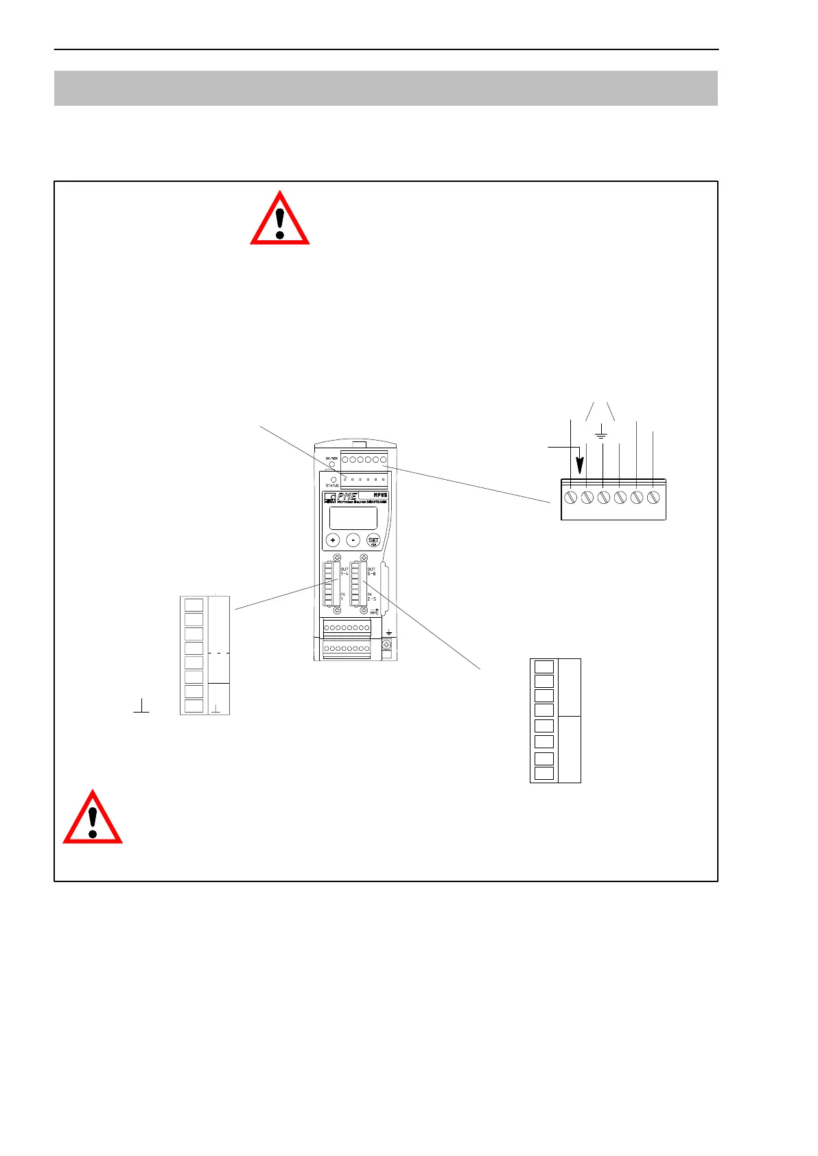
5.3 Supply voltage and control inputs/outputs
Four (MP85) or three (MP85DP) connectable screw terminals are available for
connecting the supply and the control inputs/outputs.
0 V
SYNC
Screw terminal 3
(control inputs/outputs)
LH
Screw terminal 1
(voltage supply CAN bus,
synchronization)
Connecting the voltage
supply:
The MP85/MP85DP module must be connected to an
external supply voltage of 18−30 V (24 V
nom
).
WARNING
D The wire ends of the voltage supply must be provided with
end sleeves for strands.
D Attach the wire ends to screw terminal 1.
D Insert the screw terminal in the top socket.
D Activate the voltage supply.
IN = digital input OUT = digital output
CAUTION
If there is a power failure at the MP85/MP85DP module, all
the control outputs will be set to 0 V.
24 V
Labeling
Screw terminal 2
CAN
(CAN adapter; assignment as
screw terminal 1)
Screw terminal 4 (MP85 only)
(control inputs/outputs)
Out 1
Out 2
Out 3
Out 4
0V
24V
IN 1
Out 5
Out 6
Out 7
Out 8
IN 2
IN 3
IN 4
IN 5
IN
1
2
OUT
3
4
0V
24V
IN
1
5
6
OUT
7
8
2
3
IN
5
4
Fig. 5.1: Screw terminal assignment
The screw terminals are coded so that there will be no confusion when
attaching them to the sockets. Sockets are equipped with coding tabs, screw
terminals 1 and 2 with coding pins.
In the case of screw terminals 3 and 4, the coding lugs are broken off. Screw
terminals 3 and 4, 5 and 6, each have different grid dimensions.