35
PME-MP85
A0897−3.4 en HBM
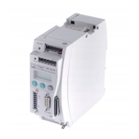
5.5 CAN interface
The CAN bus is connected via screw terminal 1. A maximum of 32 CAN
nodes can be connected in one bus segment (under CANopen specification).
The CAN bus needs a terminating resistance of 120 Ω in the first and last bus
nodes. The bus line must have no more than two terminating resistances. A
terminating resistance is integrated in the MP85DP module and is activated
by toggle switch S2.
Low High
1st device
Fig. 5.7: Connecting the CAN interface
CAN high
CAN low
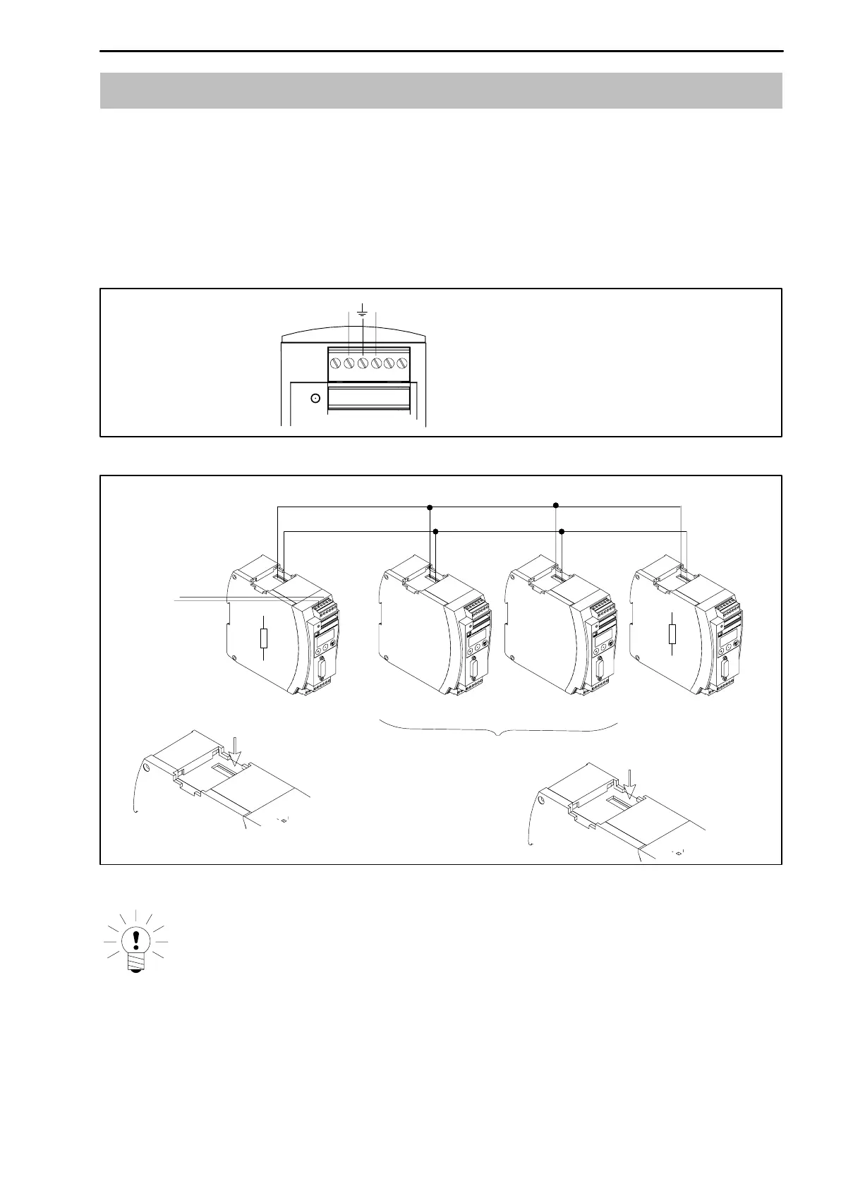
CAN connection
as per Fig. 5.7
First device in
the bus line
Last device in
the bus line
Switch in the
terminating resistance
here (toggle switch)
Do not switch in the
terminating resistance
Switch in the
terminating resistance
here (toggle switch)
Fig. 5.8: CAN bus mode with several modules (max. 32 according to the standard)
NOTE
If the first or last device in the bus line is not a PME module, a 120 W
resistance must be switched in to each of these external devices.