30
PME-MP85
A0897−3.4 enHBM
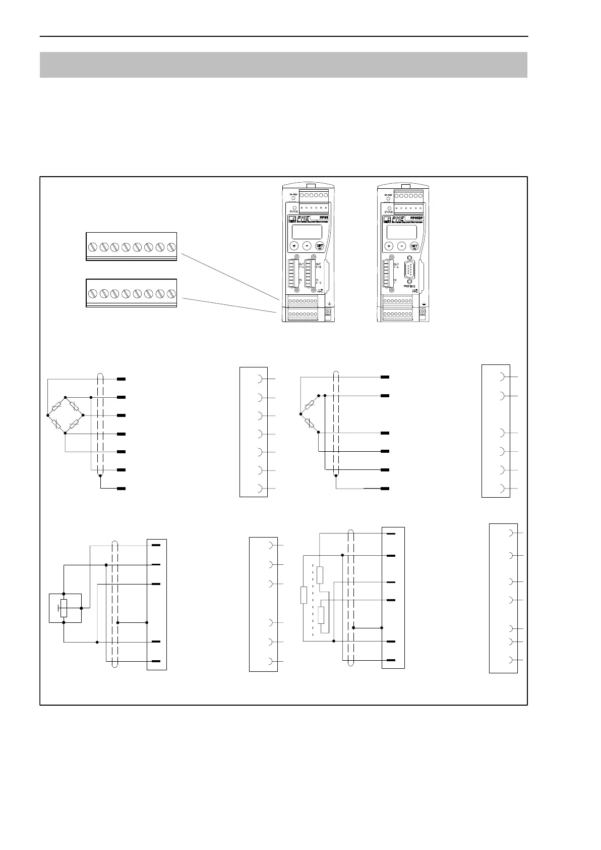
5.4 Transducer
2 transducers can be independently connected at screw terminals 5 and 6.
5.4.1 Transducers with carrier frequency excitation
In “carrier frequency amplifier” mode, the following transducer types can be
connected:
YE
S.G. and inductive full bridges,
piezoresistive transducers
1
2
4
6
Hous.
5
3
WH
BK
RD
BU
GN
GY
YE
Cable core colors:
WH= white; BK= black; BU= blue; RD= red; YE= yellow; GN= green; GY= gray
1
2
4
5
3
1
2
3
Potentiometric transducer *
)
1
2
4
6
Sensor circuit (−)
Cable shield
1
2
4
5
3
WH
BK
BU
GN
GY
Sensor circuit (−)
Sensor circuit (+)
Cable shield
S.G. and inductive half bridges
LVDT transducer
Measurement
signal (+)
Measurement
signal (+)
Excitation voltage (−)
Excitation
voltage (−)
Excitation voltage (+)
Measurement
signal (−)
Sensor circuit (+)
Hous.
5
3
Hous.
Hous.
Excitation
voltage (+)
Sensor circuit (−)
Cable shield
Measurement
signal (+)
Excitation
voltage (−)
Excitation
voltage (+)
Sensor circuit (+)
Sensor circuit (−)
Cable shield
Measurement
signal (+)
Excitation
voltage (−)
Excitation
voltage (+)
Sensor circuit (+)
Measurement
signal (−)
MP85
Screw terminals 5 and 6
for transducer connection
MP85DP
SENSOR X
18
SENSOR Y
18
Fig. 5.3: Connection of different transducers in “carrier frequency amplifier” mode
*
)
Function halfbridge