31
PME-MP85
A0897−3.4 en HBM
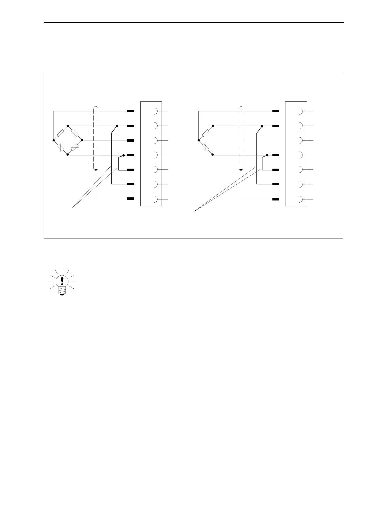
When connecting a transducer in four-wire technology, the sensor circuits
must be linked to the relevant bridge excitation circuit (pin 3 with pin 2 and pin
5 with pin 4)
1)
.
Cable core colors: WH= white; BK= black; BU= blue; RD= red; YE= yellow; GN= green; GY= gray
1
2
4
6
Hous
.
5
3
WH
BK
RD
BU
YE
Feedback bridges for four-wire technology
Four-wire connection:
Full bridge
1
2
4
6
Hous
.
5
3
WH
BK
GN
BU
YE
Four-wire connection:
Half bridge
GY
Fig. 5.4: Transducer connection in four-wire technology
NOTE
To connect the transducers, use standard cable from HBM or another
shielded, low-capacitance measurement cable. Connect the shield of
each transducer cable via the shortest possible lead (t5 cm) and a
blade connector (4.8 mm; “Faston”) to the right of screw terminal 6. This
ensures EMC protection.
1)
For cable lengths >50 m, instead of feedback bridges, a resistance with half the value of the bridge
resistance (R
B
/2) must be activated at the transducer. If the transducers are calibrated in a six-wire circuit,
the resistances must be activated directly into the sensor circuit.