10
9
8
7
6
5
4
3
2
1
Appendix
Reference
Guides
Alarms and
Emergencies
Patient
Management
Surgical
Implant and
Explant
Monitor
Peripherals
and
Accessories
HVAD
®
Pump Overview
Introduction
52 HVAD® Instructions for Use
2.1 HVAD
®
Pump and Surgical Tools (continued)
Surgical Tools and Accessories are Provided Sterile Surgical Implantation.
Figure 25: Surgical Tools
1. Tunneler – to tunnel the pump’s percutaneous driveline
through the skin to the exit site
2. Sewing ring wrench – to tighten the screw on the
sewing ring
3. Driveline cover – to cover the driveline connection to
the controller
4. Apical coring tool – to core the LV apex
5. Hex driver
to the HVAD
®
Pump
All tools and accessories used during implantation are for single-use only
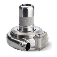
Figure 26: Components used at Implant
1. HVAD
®
Pump
2. Out ow graft
3. Sewing ring
4. Driveline cap
5. Strain relief
6. In ow cap
7. Driveline extension cable
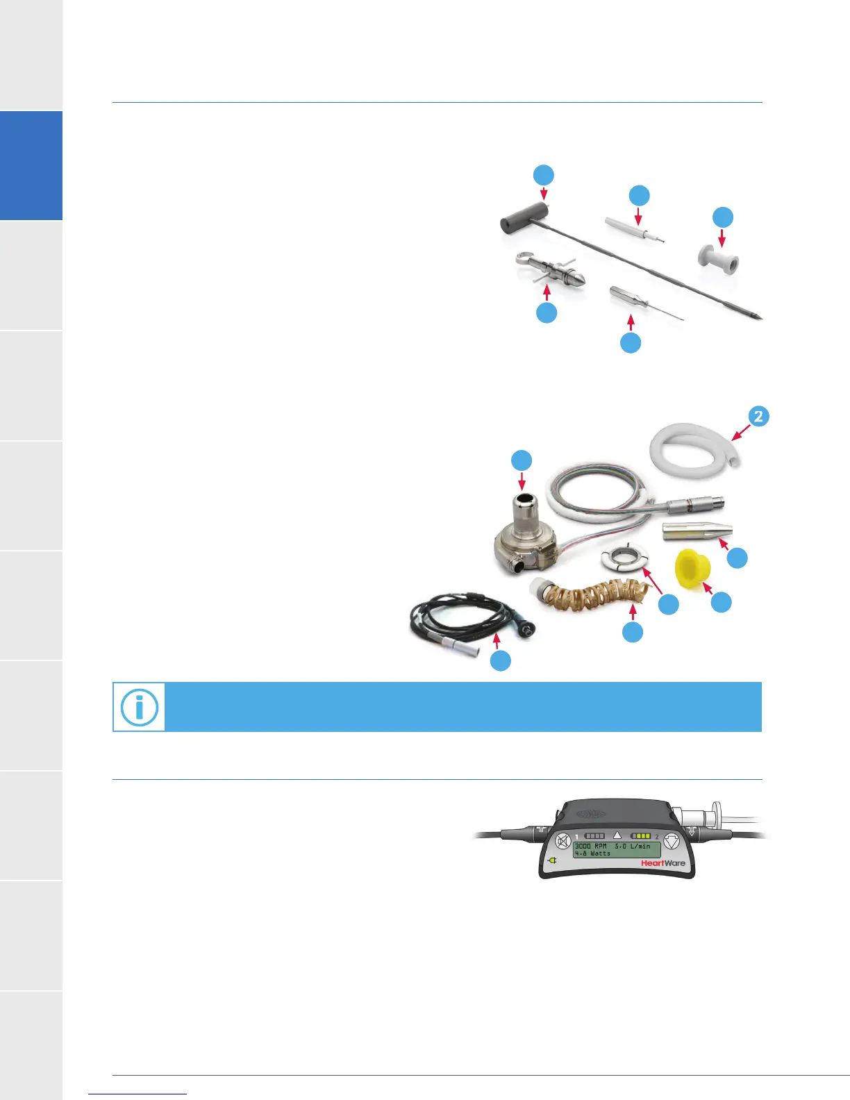
2.2 HVAD
®
Controller
The controller (Figure 27) is a microprocessor unit that
controls and manages HeartWare
™
HVAD
™
System
operation. It sends power and operating signals to
the blood pump and collects information from the
pump. The percutaneous driveline is connected to the
controller, which must always be connected to two
power sources - an AC adapter or DC adapter and/
or rechargeable batteries. The controller’s internal, non-
replaceable, rechargeable battery is used to power an
disconnected. The controller interfaces with the monitor
through a data port.
4
5
1
2
3
For additional information on implantation, see Section 6.0.
4
6
5
1
2
3
7
Figure 27
Figure 26
Figure 25