059327–00 REV. C
HEAT-TIMER CORP.
|
17
NOTE
The Flow Prove switch must be an isolated contact switch.
04 INSTALLATION INSTRUCTIONS
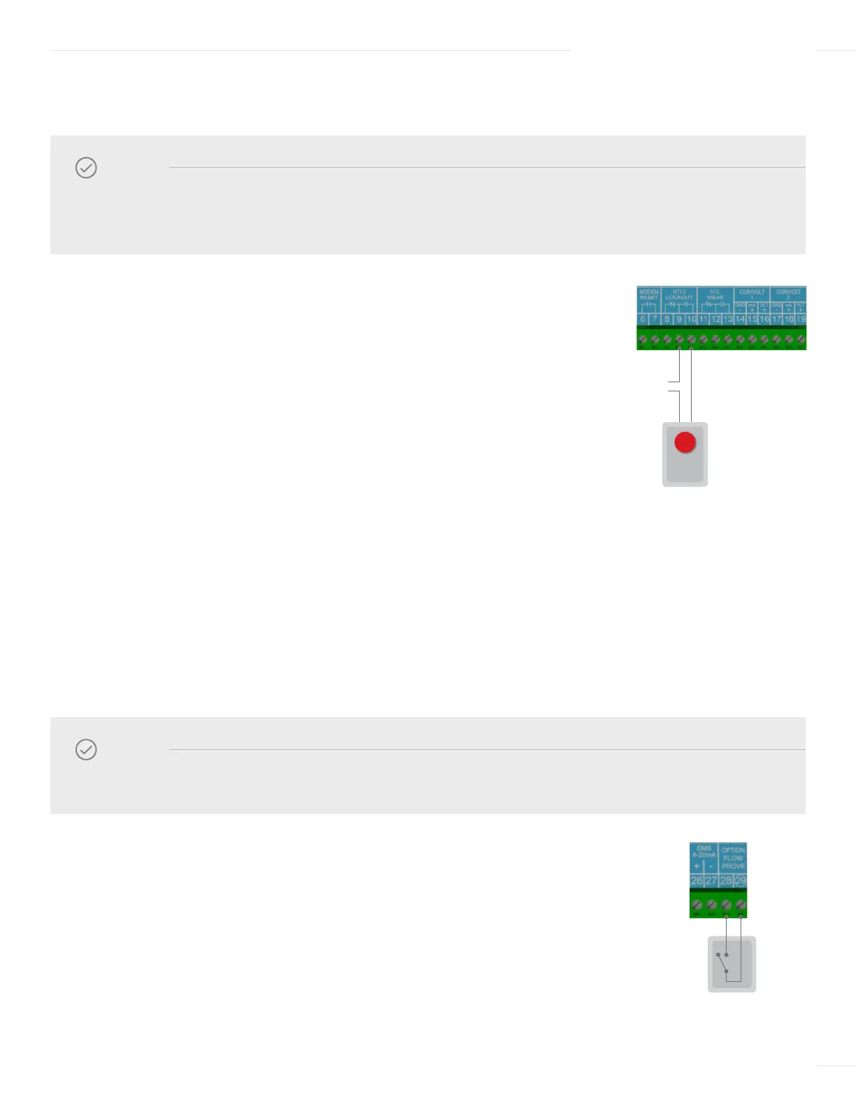
WIRING THE HTLV LOCKOUT ALARM (OPTIONAL)
WIRING THE FLOW PROVE (OPTIONAL)
1 Run the alarm wire and the external power source wire through knockouts located
on the bottom of the ETS-LT Control Module enclosure.
2 To connect a N.O. alarm device (requires switch closure to trigger):
a Connect the alarm device wire to terminal 9 on the ETS-LT
Control module.
b Connect the external power source wire to terminal 8 on the ETS-LT
Control module.
c Connect the other alarm device wire to the external power source.
3 To connect a N.C. alarm device (requires switch open to trigger):
a Connect the alarm device wire to terminal 10 on the ETS-LT Control
Module module.
b Connect the external power source wire to terminal 9 on the ETS-LT
Control module.
c Connect the other alarm device wire to the external power source.
1 Run the Flow Prove wires through a knockout located on the bottom of the ETS-LT
Control Module enclosure.
2 Connect one wire to terminal 28 on the ETS-LT Control module.
3 Connect the other wire to terminal 29 on the ETS-LT Control module.
NOTE
The ETS-LT Control Module does not source power to the HTLV Lockout terminals. An external power
source is required and must be connected in series as shown in the diagram.
120 VAC
Vis-U-Alarm
PROVE