22
English
Foratotalcablelength(connectingcableofthe
chargingsystemandvehiclechargingcable)ofup
to5m,thePEconductorresistancemustnotexceed
300mΩ.Ifthecablesarelonger,allowancesmust
be added in accordance with the applicable national
regulations. In any case, the resistance must never
exceed1Ω.
• Insulation test
The charging system is equipped with a discon-
necting relay and therefore requires two insulation
measurements. The charging system must be discon-
nected from the mains for this purpose. Therefore,
switch off the mains voltage at the circuit breaker in
the building’s electrical cabinet before performing
the measurement.
» First measurement on the primary side of the
charging system
On the primary side of the charging system, meas-
ure the insulation resistance at the connection
point of the charging system’s supply cable in the
building’s electrical cabinet. The value must not be
lessthan1MΩ.
The charging system is equipped with an
overvoltage protection device. This may be
taken into account when performing the
measurement.
» Second measurement on the secondary side of
thecharging system
To do this, connect the charging coupler to a
test adapter for vehicle simulation according
toENIEC61851-1.Performtheinsulationmeas-
urement via the measuring sockets on the test
adapter.Thevaluemustnotbelessthan1MΩ.
Alternatively,thedifferential-currentmethodin
combination with measuring the PE conductor
currentcanbeused.Avalueof3.5mAmustnot
beexceededineithercase.Toperformthese
measurements, connect the charging coupler
toatestadapterforvehiclesimulationaccording
toENIEC61851-1.Themeasurementsmustbeper-
formedinadapterstateC.Thedifferential-current
measurement must be performed at the connec-
tion point of the charging system’s supply cable in
the building’s electrical cabinet.
Depending on the measuring instrument
used, it might not be possible to perform
thefollowing measurement on the adapter.
In this case, perform the test at the connec-
tion terminals.
• Testing the switch‑off condition in the event of
ashort circuit (Z
L-N
)
To perform these measurements, connect the charg-
ing coupler to a test adapter for vehicle simulation
accordingtoENIEC61851-1.Themeasurementsmust
beperformedinadapterstateC.Performthemeas-
urements at the test adapter’s measuring sockets.
The values in accordance with the selected circuit
breaker must be observed.
• Testing the switch‑off condition in the event of the
RCD tripping
To perform these measurements, connect the charg-
ing coupler to a test adapter for vehicle simulation
accordingtoENIEC61851-1.Themeasurementmust
beperformedinadapterstateC.Performthemeas-
urement at the measuring sockets of the test adapter
using a suitable measuring instrument. The values in
accordancewiththeselectedRCDandthenetwork
must be observed.
• Testing the integrated DC residual current detection
To perform these measurements, connect the charg-
ing coupler to a test adapter for vehicle simulation
accordingtoENIEC61851-1.Themeasurementsmust
beperformedinadapterstateC.Performthemeas-
urements at the test adapter’s measuring sockets
using a suitable measuring instrument. The charging
system must disconnect the charging coupler
fromthemainswhentheresidualcurrentexceeds
6mADC.Thefaultdisplayonthechargingsystem
must respond.
• Testing the upstream RCD
TheupstreamRCDmustbetestedattheconnection
point of the charging system’s supply cable in the
building’selectricalcabinet.TheRCDmusttripin
accordance with the national regulations.
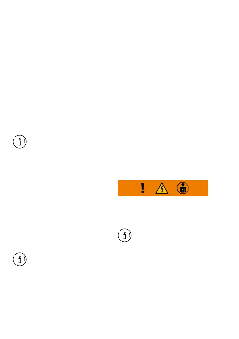
1.6 Information about signs, symbols and
labelling
Hazard warning:
Information about a possibly hazardous situation that
couldbefatalorresultinsevereinjuriesifthesafety
measuresarenotobserved.Allworktobeconductedby
skilled personnel only.
Note:
supplementary information.
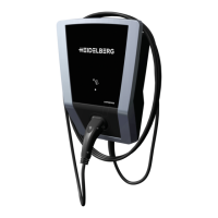
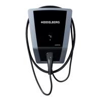
1.7 Protective devices
The following components (Fig.11) are protective
devices:
No.1housing,no.5couplerholder,no.6chargingcou-
pler,no.7chargingcable
Checking the protective devices
» 1.Visuallyinspecttheprotectivedevicesfordamage
before every charging process.
» 2.Haveaqualiedelectricianperformtheelectrical
function tests at regular intervals in compliance
with the national regulations.
 Loading...