41
NOTE
Always ensure to reinstall the drain tube after
draining the deposit.
(1) Drain tube
1
Excessive valve clearance will cause noise, and
little or no clearance will prevent the valve
from closing and cause valve damage and
power loss. Check valve clearance at the
specified intervals (page 33).
VALVE CLEARANCE ADJUSTMENT
The checking or adjustment of valve clearance
should be performed while the engine is cold.
The clearance will change as the engine
temperature rises.
NOTE
• Remove the fuel tank cover (page 59).
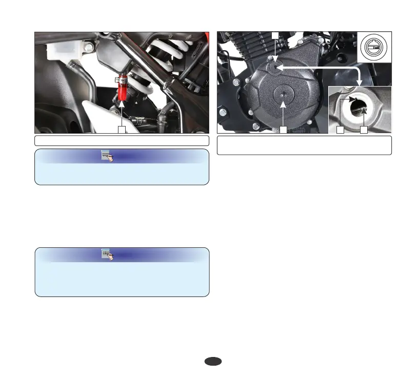
• Remove the crankshaft hole cap (1) and
timing hole cap (2).
• Remove the cylinder head cover.
This condition can be determined by moving
the rocker arms. If they are free, it is an
indication that the valves are closed and the
piston is in compression stroke. If they are
tight, the valves are open, rotate the flywheel
360° anticlockwise and realign the “T” mark
with the index mark.
The adjustment must be made when the
piston is at top dead center and both the inlet
and exhaust valves are closed.
• Rotate the flywheel anticlockwise until the
“T” mark (3) on the flywheel coincides with
the index mark (4) on the left crankcase
cover. In this position the piston will either
be on the compression or exhaust stroke.
•
Check the clearance by inserting the feeler
gauge (5) between the adjusting screw (6)
and valve stem (7).
41
(1) Crankshaft hole cap (2) Timing hole cap
(3) 'T' mark (4) Index mark
3
2