Hex ezCAN for CAN-bus-equipped Motorcycles
_________________________________________________________________________________________________
_________________________________________________________________________________________________
© Hex Innovate (UK) Ltd. Page 50 of 60 ezCAN 2408.x
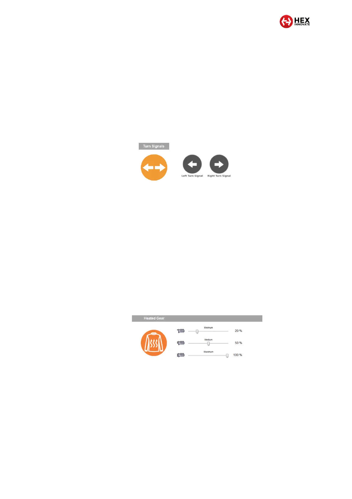
5.3.5 Operating auxiliary turn signals
Depending on its configuration, an auxiliary turn signal will be active as
a running light or marker light whenever the ignition switch is ON, active
as a turn signal whenever the turn signal for that side is switched on, and
active as an auxiliary hazard light whenever the hazard lights are switched
on. To use this feature, set one or more power circuits to power auxiliary
left or right turn signals. The Turn Signals section of the ezCAN
configuration software will be shown (below, left). This section of the
software is associated with the Left Turn Signal and Right Turn Signal
circuit configuration options (below, right).
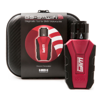
5.3.6 Operating heated gear
Heated gear is supported if:
The motorcycle has factory-installed heated grips, and
The ezCAN has software version 2009 or newer.
If a power circuit is configured as a Heated Gear power supply, the
circuit’s power is regulated using the motorcycle’s factory heated grip
controls. Depending on make and model, the motorcycle’s heated grip
control may have two, three or five heat level settings. Output power for
heated gear can be selected individually for each of the heat levels. To set
the Heated Gear power level for each of the heated grip settings, click-
and-drag the slider between 0% (off) and 100% (maximum power)
(below).
5.3.7 Disabling an ezCAN power circuit
If any ezCAN power circuit is not needed, you can disable it by opening
the Circuit Functions dialogue, selecting the icon for the relevant circuit,
and clicking the Disable circuit icon. If a power circuit is disabled, seal the
female power circuit connector with one of the blanking plugs supplied
with the kit.