Operation IRP40.02
44
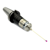
2.6 Aligning Probe in Shank with 90°Adapter
1. Loosen adjustment screws "A" (4x) then tighten lightly.
2. Loosen clamping screws "C" (2x) then tighten lightly.
3. Adjust the angular position of the probe using cylinder screw AF4 mm to (±5°).
4. Tighten the clamping screws "C" (2x).
5. Alternately tighten the adjustment screws "A" (4x).
6. Calibrate the probe.
Fig. 11 Aligning probe in shank with 90°adapter
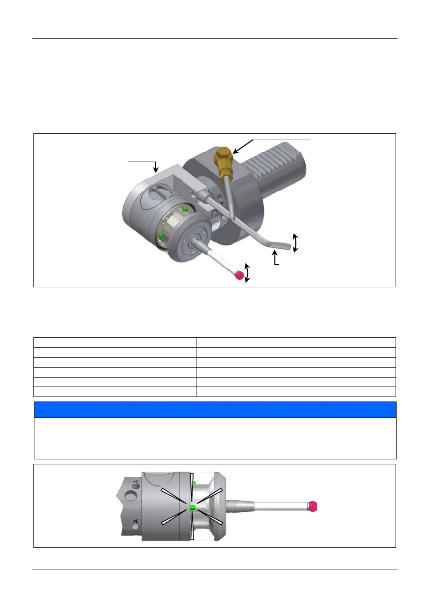
2.7 Optical Status Display
Subsequent table gives an overview of the blinking patterns of the LEDs (Fig. 12) and their meaning.
LED permanently blue (approx. 5s)
Touch probe initializes after inserting batteries
Touch probe is transmitting signals
Collision of the touch probe in Z probing direction (Z-Crash)
NOTICE
Risk of measuring inaccuracies!
After collision of the touch probe in Z probing direction, the basic measuring functions are still working.
Nevertheless, the initial accuracy can not be guaranteed in such a case. After a Z-collision It is recommended to
send the probe to the manufacturer for inspection/repair!
Fig. 12 Optical status display
Air jet with rotary joint
for
shank VDI
-SWV
Hexagon key AF4 mm
(3489)
shank
D20-VDI-90
 Loading...