Chapter 6. Parameter Setting
6-7
6.2.1 Digital loader signal display
(1) Input signal display
The status of input contact recognized within the system is indicated with either "0" or "1".
Therefore, if the status input from the external sources is different from the displayed
information, it indicates problem on the input system. As each signal carries different meaning,
explanation is provided through examples below.
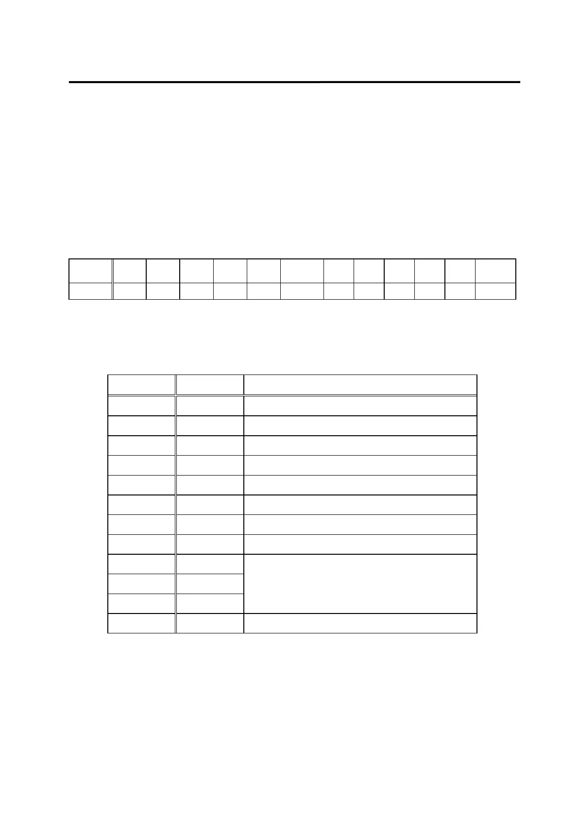
(Example of display)
Signal
ALM
RST
STOP ESTOP TLIM CWLIM CCWLIM P/PI DIR SPD3 SPD2 SPD1 SVONEN
Display
0 0 1 0 0 1 0 0 0 0 1 1
1: Input signal operating
0: Input signal not operating
Signal Display Description
ALMRST 0 Alarm reset function not used
STOP 0 Motor stop not used
ESTOP 1 Emergency stop not used
TLIM 0 Analog torque limit not used
CWLIM 0 CW direction rotation not possible
CCWLIM 1 CCW direction rotation possible
P/PI 0 Operates as PI control
DIR 0 Rotates in the direction of command
SPD3 0
SPD2 0
SPD1 1
Internal command speed 1 used
SVONEN 1 Servo motor start command operating
The above examples are based on the current status of each signal. System operates in
reverse if signals are in opposite status.