14
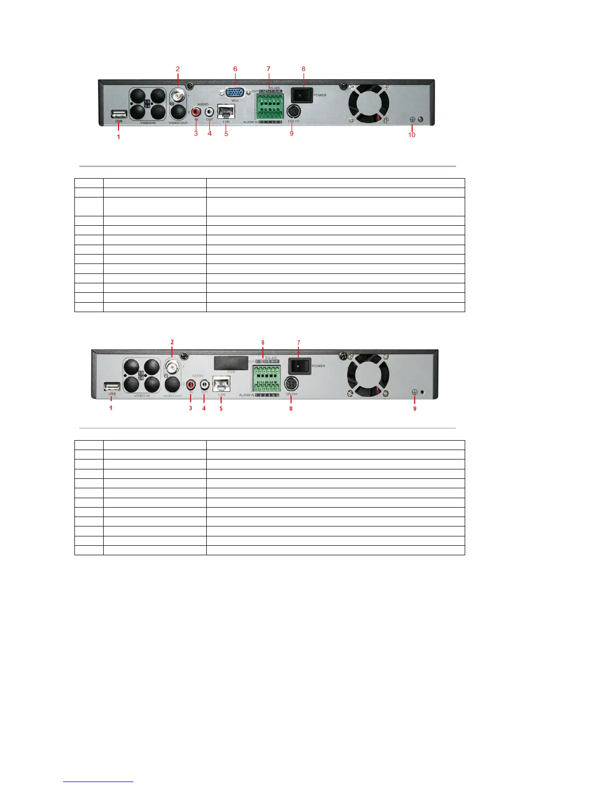
Figure 8. Rear Panel of DS-7604NI-S
No. Item Description
1 USB Interface Connector for USB devices
2 VIDEO OUT BNC connector for video output. If VGA output has been connected, then the
VIDEO OUT port provides no output.
3 AUDIO IN RCA connectors for analog audio input
4 AUDIO OUT RCA connector for audio output
5 LAN Connector for LAN (Local Area Network)
6 VGA DB15 connector for VGA output. Display local video output and menu
7 RS-485 Interface Connector for RS-485 devices. T+, T- pin connects to PTZ
ALARM IN Connector for alarm input (up to 4 channels)
ALARM OUT Connector for alarm output (1 channel)
8 POWER Switch for turn on/off the device
9 12V 12VDC power supply
10 GND Ground (needs to be connected when DVR startup)
Figure 9. Rear Pane of DS-7604NI-S/M
No. Item Description
1 USB Interface Connector for USB devices
2 VIDEO OUT BNC connector for video output
3 AUDIO IN RCA connectors for analog audio input
4 AUDIO OUT RCA connector for audio output
5 LAN Connector for LAN (Local Area Network)
6 RS-485 Interface Connector for RS-485 devices. T+, T- pin connects to PTZ
ALARM IN Connector for alarm input (up to 4 channels)
ALARM OUT Connector for alarm output (1 channel)
7 POWER Switch for turn on/off the device
8 12V 12VDC power supply
9 GND Ground(needs to be connected when DVR startup)
 Loading...